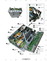
Pioneer VSX-816-S Service Manual - Page 114
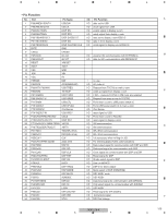
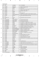
RDS power supply/XM reset. FM : Low, AM:High, H: SW YES, L: SW NO SX316 no connect
 |
View all Pioneer VSX-816-S manuals
Add to My Manuals
Save this manual to your list of manuals |
Page 114 highlights
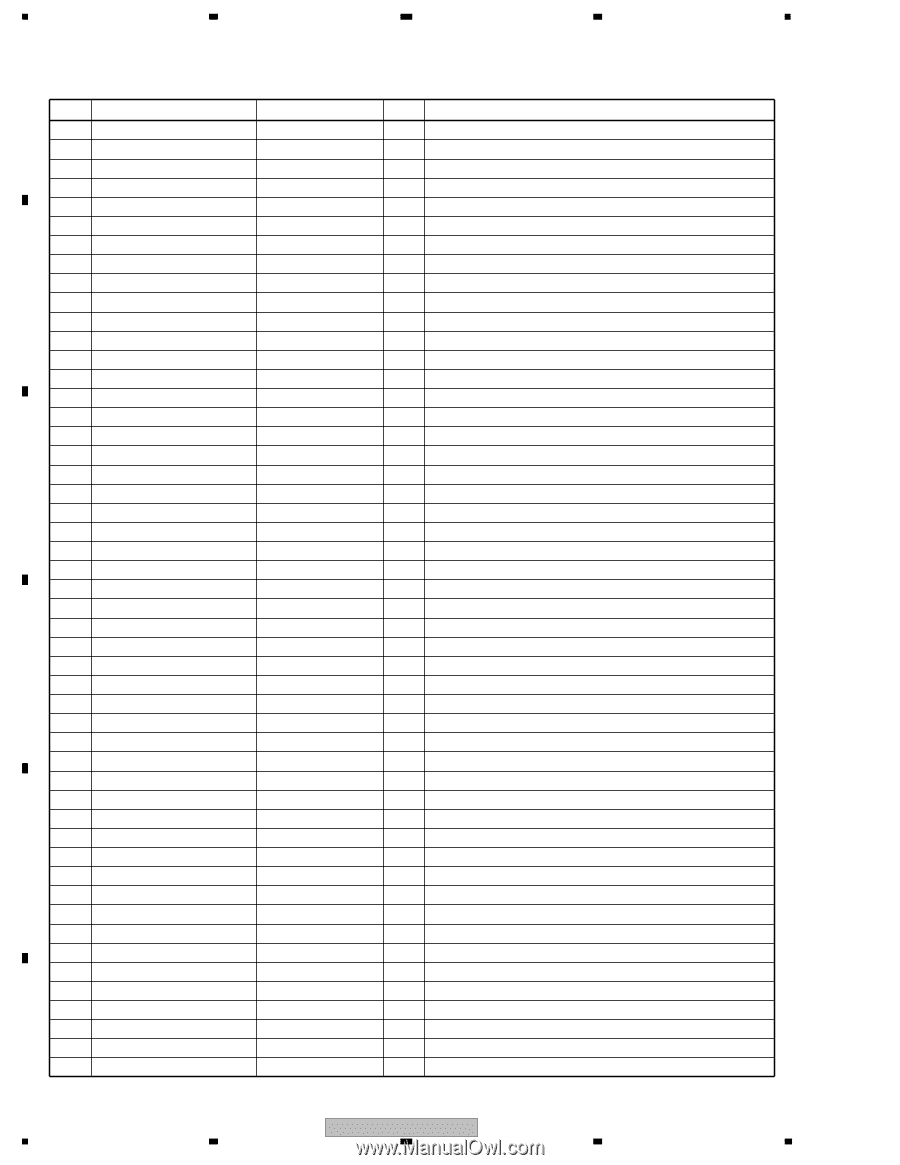
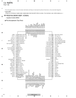
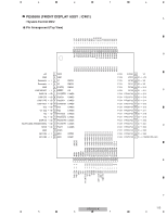
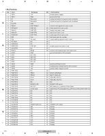
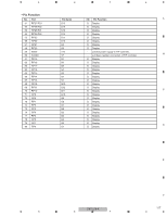
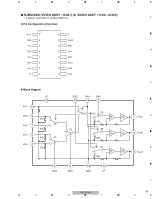
1 • Pin Function A No. Port 51 P43/A19 52 P42/A18 53 P41/A17 54 P40/A16 55 P37/A15 56 P36/A14 57 P35/A13 58 P34/A12 59 P33/A11 B 60 P32/A10 61 P31/A9 62 Vcc 63 P30/A8(/_/D7) 64 Vss 65 P27/A7(/D7/D6) 66 P26/A6(/D6/D5) 67 P25/A5(/D5/D4) 68 P24/A4(/D4/D3) 69 P23/A3(/D3/D2) C 70 P22/A2(/D2/D1) 71 P21/A1(/D1/D0) 72 P20/A0(/D0/_) 73 P17/D15/INT5 74 P16/D14/INT4 75 P15/D13/INT3 76 P14/D12 77 P13/D11 78 P12/D10 79 P11/D9 D 80 P10/D8 81 P07/D7 82 P06/D6 83 P05/D5 84 P04/D4 85 P03/D3 86 P02/D2 87 P01/D1 88 P00/D0 E 89 P107/AN7/KI3 90 P106/AN6/KI2 91 P105/AN5/KI1 92 P104/AN4/KI0 93 P103/AN3 94 P102/AN2 95 P101/AN1 96 AVSS 97 P100/AN0 98 VREF F 99 AVcc 100 P97/ADTRG/SIN4 114 1 2 3 4 Pin Name I/O Pin Function NECK_SEL I/O For 8ohm spk impedance: "H at Adv Surr,Standard,5.1Multich,speaker A+B(7ch model). For 6 ohm spk impedance: L XMDACRST I/O RESET of 2chDAC for XM AMUTE I/O System mute RY_B I/O Speaker B relay-on / OFF at 916, 816 and 516.This RY_B is used for SW relay at 316. RY_C/R I/O Rear one / center relay-on / OFF RY_A I/O Speaker A relay-on / OFF XM ERR I/O RY-AC I/O AC relay on/off VIDEO4 I/O NJM2296 control (VIDEO input select) (SX316 no connect) LOW_CONSUMPTION I/O When 1 minutes passed after power off and then go into stop mode and port L, else H. EVR CLK I/O Clock signal for Function and E-volume 5V EVR DT I/O Data signal for Function and E-volume GND COMP VIDEO INH I/O Component terminal control COMP VIDEOB I/O Component terminal control COMP VIDEOA I/O Component terminal control SWDET I/O "H": SW YES, "L": SW NO (SX316 no connect) VIDEO3 I/O NJM2296 control (VIDEO input select) (SX316 no connect) VIDEO2 I/O NJM2296 control (VIDEO input select) (SX316 no connect) VIDEO1 I/O NJM2296 control (VIDEO input select) (SX316 no connect) DC PROTECT I/O Amplifier DC detection. H:Normal, L:Abnormal OL DET I/O Amplifier overload detection. H:Normal, L:Abnormal DSP OVERLOAD I/O ANALOG OVER LOAD detect (H : detect) RDS CLK/XM LOWSPEED I/O RDS clock in signal/XM Lowspeed RDS DT/Link ACTIVE(XM) I/O RDSdata in signal/XM Link Active RDS FM+/XM RST I/O RDS power supply/XM reset. FM : Low, AM:High WAKE UPB(XM) I/O XMDT for communication XM Signal Sw I/O CLK,DT, etc. XM/DIR selector (XM : High) XM Common Select I/O XM TUNER DO I/O Data input signal for tuner contorol TUNER CLK I/O Clock signal for tuner contorol TUNER DI I/O Data output signal for tuner contorol TUNER CE I/O Chip select signal for tuner contorol 6 OHM I/O if stop mode, port L, else according to setting(J model No connect) OSD RST I/O OSD CS I/O DECO MUTE I/O 1st DSP detect port XPROTECT I/O Power supply abnormal condition detection. H: Normal, L: Abnormal. MVRATT I/O Master volume ATT control (-15dB or less : L) XM POW I/O XM antenna power supply. H always. When abnormally detecting it, it makes it to L. iPod POW I/O IPod power supply. H always. When abnormally detecting it, it makes it to L. XM Fs I/O XM SIMUKE1 I/O lnput 1 to switch region SIMUKE2 I/O lnput 2 to switch region AVSS connects with VCC. HP DET I/O HP detection H:detected. VREF connects with VCC. AVCC connects with VCC. USDAO I/O data input from USB VSX-816-K 2 3 4
-
 1
1 -
2
-
3
-
4
-
5
-
6
-
7
-
8
-
9
-
10
-
11
-
12
-
13
-
14
-
15
-
16
-
17
-
18
-
19
-
20
-
21
-
22
-
23
-
24
-
25
-
26
-
27
-
28
-
29
-
30
-
31
-
32
-
33
-
34
-
35
-
36
-
37
-
38
-
39
-
40
-
41
-
42
-
43
-
44
-
45
-
46
-
47
-
48
-
49
-
50
-
51
-
52
-
53
-
54
-
55
-
56
-
57
-
58
-
59
-
60
-
61
-
62
-
63
-
64
-
65
-
66
-
67
-
68
-
69
-
70
-
71
-
72
-
73
-
74
-
75
-
76
-
77
-
78
-
79
-
80
-
81
-
82
-
83
-
84
-
85
-
86
-
87
-
88
-
89
-
90
-
91
-
92
-
93
-
94
-
95
-
96
-
97
-
98
-
99
-
100
-
101
-
102
-
103
-
104
-
105
-
106
-
107
-
108
-
 109
109 -
 110
110 -
 111
111 -
 112
112 -
 113
113 -
 114
114 -
 115
115 -
 116
116 -
 117
117 -
 118
118 -
 119
119 -
120
-
121
-
122
-
123
-
124
-
125
-
126
-
127
-
128
-
129
-
130
-
131
-
132
-
133
-
134
-
135
-
136
-
137
-
138
-
139
-
140
-
141
-
142
-
143
-
144
 |
 |