Pioneer VSX-816-S Service Manual - Page 131
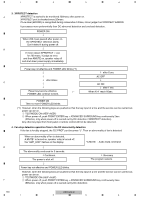
AMPLIFIER FAILURE DIAGNOSIS FLOW CHART, When releasing the lock state of power key before repair - troubleshoot
 |
View all Pioneer VSX-816-S manuals
Add to My Manuals
Save this manual to your list of manuals |
Page 131 highlights
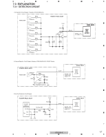
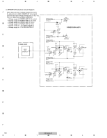
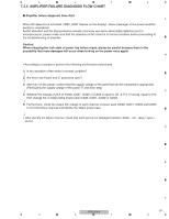
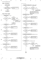
5 6 7 8 7.3.3 AMPLIFIER FAILURE DIAGNOSIS FLOW CHART Amplifier failure diagnosis flow chart A When DC detection is activated ("AMP_ERR" flashes on the display), failure (damage) of the power amplifier section is considered. As DC detection and fan stop protection circuits commonly use same abnormality detection port in microprocessor, please make sure that the operation of fan motor is in normal condition before proceeding to the troubleshooting of amplifier. Caution: When releasing the lock state of power key before repair, please be careful because there is the possibility that more damages will occur when turning on the power once again! B • According to a symptom, perform the following confirmation beforehand. 1) Is the operation of fan motor in normal condition? ↓ 2) Are there any Fuses and IC protectors open? ↓ 3) After turn on the power, confirm that the supply voltage of the point that can be measured is appropriate. (Particularly the supply voltage of the power Tr and drive step) ↓ C 4) Whether the voltage of pin3 of IC600, IC601, IC602 or IC603 is equal to (VL-0.7V). If not (eg, equal to VH), then change the corresponding power pack IC600, IC601, IC602 or IC603. ↓ 5) Furthermore, check the output DC voltage of each channel of power pack IC600, IC601, IC602 and IC603 to limit the failure channel and identify the defect power pack. ↓ • After identify the failure channel, check that each part is not damaged (resistor, diode... etc. value / open / short) D E F VSX-816-K 131 5 6 7 8
-
 1
1 -
2
-
3
-
4
-
5
-
6
-
7
-
8
-
9
-
10
-
11
-
12
-
13
-
14
-
15
-
16
-
17
-
18
-
19
-
20
-
21
-
22
-
23
-
24
-
25
-
26
-
27
-
28
-
29
-
30
-
31
-
32
-
33
-
34
-
35
-
36
-
37
-
38
-
39
-
40
-
41
-
42
-
43
-
44
-
45
-
46
-
47
-
48
-
49
-
50
-
51
-
52
-
53
-
54
-
55
-
56
-
57
-
58
-
59
-
60
-
61
-
62
-
63
-
64
-
65
-
66
-
67
-
68
-
69
-
70
-
71
-
72
-
73
-
74
-
75
-
76
-
77
-
78
-
79
-
80
-
81
-
82
-
83
-
84
-
85
-
86
-
87
-
88
-
89
-
90
-
91
-
92
-
93
-
94
-
95
-
96
-
97
-
98
-
99
-
100
-
101
-
102
-
103
-
104
-
105
-
106
-
107
-
108
-
109
-
110
-
111
-
112
-
113
-
114
-
115
-
116
-
117
-
118
-
119
-
120
-
121
-
122
-
123
-
124
-
125
-
 126
126 -
 127
127 -
 128
128 -
 129
129 -
 130
130 -
 131
131 -
 132
132 -
 133
133 -
 134
134 -
 135
135 -
 136
136 -
137
-
138
-
139
-
140
-
141
-
142
-
143
-
144
 |
 |