Pioneer VSX-816-S Service Manual - Page 135
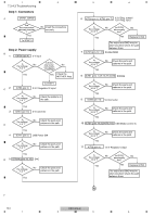
Step 3: Operation of USB Media control IC, IC701, IC953 5 V, CN702
 |
View all Pioneer VSX-816-S manuals
Add to My Manuals
Save this manual to your list of manuals |
Page 135 highlights
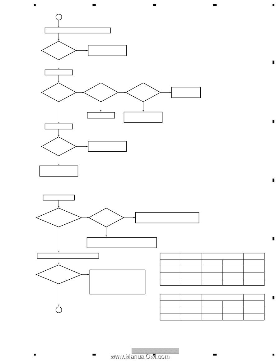
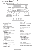
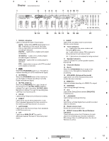
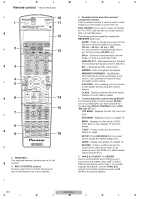
5 6 7 A 12 IC701 (pins 7,24,41,71,77,87,109,119) USB Media control IC Is the voltage 1.8 V ? No Check the parts and patterns in the path. Yes 13 IC771 (pin 1) USB Power SW output 8 A Is the voltage 5 V ? No Is pin 4 No Is pin 14 No Check the (CTL) of IC771 high? (CTL) of CN702 high? MOTHER Assy. B Yes Yes Yes Replace IC771. 14 CN701 (pin 1) USB Bus power Check the parts and patterns in the path. Is the voltage 5 V ? No Check the parts and patterns in the path. C Yes Power supply is OK. To STEP 3 Step 3: Operation of USB Media control IC Note: Please confirm it with the USB memory connected for the content. IC701 (pins 74,75) XIN/XOUT D Does the crystal oscillator No at 12 MHz Is XRST high? No XRST must be high during operation. Check the MOTHER Assy. ? Yes Yes Check the parts and patterns in the path. Replace X701, etc. Fig. 1 USCS/USCLK (Refer to Fig. 1 and 2) IC701 IC953 (5 V → 3 V) CN702 Are USCS and USCLK high? Yes No USCS and USCLK should be high during operation. Check the pattern in the path. Check the MOTHER Assy. Replace IC762, etc. XRST pin 72 pin 3 pins 1,2 pin 5 USCS pin 121 pin 11 pins 12,13 pin 9 E HREQ pin 122 pin 6 pins 4,5 pin 12 USDAI pin 118 pin 8 pins 9,10 pin 10 Fig. 2 IC701 IC951 (3 V → 5 V) CN702 USCLK pin 116 pins 4,5 pin 6 pin 7 B USDAO pin 115 pins 9,10 pin 8 pin 11 TREQ pin 123 pins 12,13 pin 11 pin 13 F VSX-816-K 135 5 6 7 8
-
 1
1 -
2
-
3
-
4
-
5
-
6
-
7
-
8
-
9
-
10
-
11
-
12
-
13
-
14
-
15
-
16
-
17
-
18
-
19
-
20
-
21
-
22
-
23
-
24
-
25
-
26
-
27
-
28
-
29
-
30
-
31
-
32
-
33
-
34
-
35
-
36
-
37
-
38
-
39
-
40
-
41
-
42
-
43
-
44
-
45
-
46
-
47
-
48
-
49
-
50
-
51
-
52
-
53
-
54
-
55
-
56
-
57
-
58
-
59
-
60
-
61
-
62
-
63
-
64
-
65
-
66
-
67
-
68
-
69
-
70
-
71
-
72
-
73
-
74
-
75
-
76
-
77
-
78
-
79
-
80
-
81
-
82
-
83
-
84
-
85
-
86
-
87
-
88
-
89
-
90
-
91
-
92
-
93
-
94
-
95
-
96
-
97
-
98
-
99
-
100
-
101
-
102
-
103
-
104
-
105
-
106
-
107
-
108
-
109
-
110
-
111
-
112
-
113
-
114
-
115
-
116
-
117
-
118
-
119
-
120
-
121
-
122
-
123
-
124
-
125
-
126
-
127
-
128
-
129
-
 130
130 -
 131
131 -
 132
132 -
 133
133 -
 134
134 -
 135
135 -
 136
136 -
 137
137 -
 138
138 -
 139
139 -
 140
140 -
141
-
142
-
143
-
144
 |
 |