Pioneer VSX-816-S Service Manual - Page 128
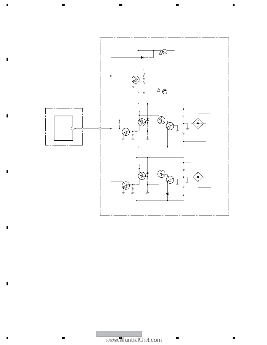
XPROTECT Detection Circuit Diagram, POWER PACK ASSY, MAIN ASSY
 |
View all Pioneer VSX-816-S manuals
Add to My Manuals
Save this manual to your list of manuals |
Page 128 highlights
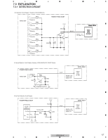
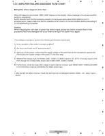
1 2 3 4 4. XPROTECT Detection Circuit Diagram A When below 6 kind of voltage supply become to be short circuit to GND, XPROTECT circuit work and U-P input port voltage change from +5 V to 0 V. The U-P detect this condition as ERROR. • Voltage supply to POWER AMP IC (V neck+) • Voltage supply to POWER AMP IC (V neck-) • Voltage supply to POWER AMP IC (VH+) • Voltage supply to POWER AMP IC (VH-) • Voltage supply to +12 V REGULATOR IC • Voltage supply to -12 V REGULATOR IC B MAIN ASSY IC9001 (U-P) 89 XPROTECT C D Voltage supply to POWER AMP IC (V neck+) Q701 2SC5511(E) D713 R713 1SS133 1k D+5V Q698 R697 10k R698 33k Voltage supply to POWER AMP IC (V neck-) Voltage supply to POWER AMP IC (VH+) D+5V POWER PACK ASSY Q702 2SA2005(E) D+5V Q705(1/2) R727 10k R714 1k Q705(2/2) C709 1/50 D703 R715 10k R716 10k Q707(1/2) Q707(2/2) C703 3300 /42 C704 3300 /42 D702 D5SBA20(B) Voltage supply to POWER AMP IC (VH-) Voltage supply to +12 V REGULATOR IC D+5.6V Q807(2/2) Q808(2/2) R808 1k C806 1/50 Voltage supply to -12 V REGULATOR IC D807 R807 10k R806 10k Q807(1/2) Q808(1/2) C801 2200 /25 D806 MTZJ6.2B C802 2200 /25 D801 S1WB(A)60SD E F 128 VSX-816-K 1 2 3 4
-
 1
1 -
2
-
3
-
4
-
5
-
6
-
7
-
8
-
9
-
10
-
11
-
12
-
13
-
14
-
15
-
16
-
17
-
18
-
19
-
20
-
21
-
22
-
23
-
24
-
25
-
26
-
27
-
28
-
29
-
30
-
31
-
32
-
33
-
34
-
35
-
36
-
37
-
38
-
39
-
40
-
41
-
42
-
43
-
44
-
45
-
46
-
47
-
48
-
49
-
50
-
51
-
52
-
53
-
54
-
55
-
56
-
57
-
58
-
59
-
60
-
61
-
62
-
63
-
64
-
65
-
66
-
67
-
68
-
69
-
70
-
71
-
72
-
73
-
74
-
75
-
76
-
77
-
78
-
79
-
80
-
81
-
82
-
83
-
84
-
85
-
86
-
87
-
88
-
89
-
90
-
91
-
92
-
93
-
94
-
95
-
96
-
97
-
98
-
99
-
100
-
101
-
102
-
103
-
104
-
105
-
106
-
107
-
108
-
109
-
110
-
111
-
112
-
113
-
114
-
115
-
116
-
117
-
118
-
119
-
120
-
121
-
122
-
 123
123 -
 124
124 -
 125
125 -
 126
126 -
 127
127 -
 128
128 -
 129
129 -
 130
130 -
 131
131 -
 132
132 -
 133
133 -
134
-
135
-
136
-
137
-
138
-
139
-
140
-
141
-
142
-
143
-
144
 |
 |