Pioneer VSX-935 7.2-Channel Network AV Receiver Instruction Manual English - Page 11
Part Names, Front Panel
 |
View all Pioneer VSX-935 7.2-Channel Network AV Receiver manuals
Add to My Manuals
Save this manual to your list of manuals |
Page 11 highlights
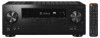
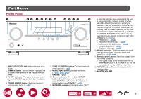
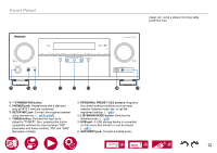
Part Names Front Panel 1. INPUT SELECTOR dial: Switch the input to be played. 2. DIMMER button: You can switch the display off or adjust the brightness of the display in three steps. 3. FL OFF indicator: This lights when you have pressed DIMMER repeatedly to turn the display off. 4. ZONE 2-ON/OFF button: Switches the multizone function on/off. ( →p92) 5. ZONE 2-CONTROL button: Controls the multizone function. ( →p92) 6. HOME MENU button: Displays the Home. ( →p107, p130, p134) 7. Display ( →p13) 8. Cursor buttons ( / / / ) and ENTER button: Select the item with the cursors, and press ENTER to confirm. Use them to tune to stations when using TUNER. ( →p69) 9. NETWORK indicator: This lights when "NET" is selected with the input selector and the unit is connected to the network. Lights up when any of the following functions is working or enabled in standby state of this unit. When this indicator is lighting, the power consumption in standby state increases, however, the increase in power consumption is minimized by entering the HYBRID STANDBY mode where only the essential circuits operate. It does not light when ZONE 2 is on, however. - HDMI CEC ( →p123) - HDMI Standby Through ( →p123) - USB Power Out at Standby ( →p125) - Network Standby ( →p125) - Bluetooth Wakeup ( →p125) 10. MCACC indicator: This lights when you have enabled the speaker calibration made with MCACC. ( →p131, p144) 11. Remote control sensor: Receives signals from the remote controller. • The signal range of the remote controller is within about 16´/5 m, at an angle of 20° on the perpendicular axis and 30° to either side. 12. RETURN button: Returns the display to the previous state. 13. MASTER VOLUME 11
-
 1
1 -
2
-
3
-
4
-
5
-
 6
6 -
 7
7 -
 8
8 -
 9
9 -
 10
10 -
 11
11 -
 12
12 -
 13
13 -
 14
14 -
 15
15 -
 16
16 -
17
-
18
-
19
-
20
-
21
-
22
-
23
-
24
-
25
-
26
-
27
-
28
-
29
-
30
-
31
-
32
-
33
-
34
-
35
-
36
-
37
-
38
-
39
-
40
-
41
-
42
-
43
-
44
-
45
-
46
-
47
-
48
-
49
-
50
-
51
-
52
-
53
-
54
-
55
-
56
-
57
-
58
-
59
-
60
-
61
-
62
-
63
-
64
-
65
-
66
-
67
-
68
-
69
-
70
-
71
-
72
-
73
-
74
-
75
-
76
-
77
-
78
-
79
-
80
-
81
-
82
-
83
-
84
-
85
-
86
-
87
-
88
-
89
-
90
-
91
-
92
-
93
-
94
-
95
-
96
-
97
-
98
-
99
-
100
-
101
-
102
-
103
-
104
-
105
-
106
-
107
-
108
-
109
-
110
-
111
-
112
-
113
-
114
-
115
-
116
-
117
-
118
-
119
-
120
-
121
-
122
-
123
-
124
-
125
-
126
-
127
-
128
-
129
-
130
-
131
-
132
-
133
-
134
-
135
-
136
-
137
-
138
-
139
-
140
-
141
-
142
-
143
-
144
-
145
-
146
-
147
-
148
-
149
-
150
-
151
-
152
-
153
-
154
-
155
-
156
-
157
-
158
-
159
-
160
-
161
-
162
-
163
-
164
-
165
-
166
-
167
-
168
-
169
-
170
-
171
-
172
-
173
-
174
-
175
-
176
-
177
-
178
-
179
-
180
-
181
-
182
 |
 |
