Poulan HDF900 Owner Manual - Page 13
Service And Adjustments
 |
View all Poulan HDF900 manuals
Add to My Manuals
Save this manual to your list of manuals |
Page 13 highlights
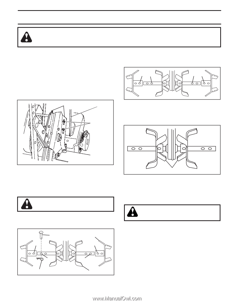
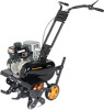
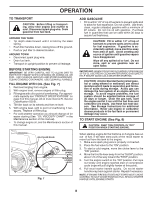
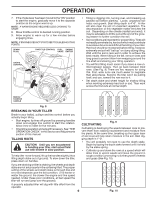
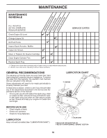
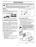
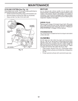
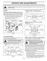
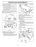
SERVICE AND ADJUSTMENTS CAUTION: Disconnect spark plug wire from spark plug and place wire where it cannot come into contact with plug. TILLER TO ADJUST HANDLE HEIGHT (See Fig. 15) Factory assembly has provided lowest handle height. Select handle height best suited for your tilling conditions. Handle height will be different when tiller digs into soil. • If a higher handle height is desired, loosen the four nuts securing handle panel to engine brackets. • Slide handle panel to desired location. • Tighten the four nuts securely. ENGINE BRACKETS HANDLE PANEL NUTS (ALSO 2 ON LEFT SIDE OF TILLER) MID-WIDTH TILLING - 24" PATH (See Fig. 17) • Assemble holes "A" in tine hubs to holes "C" in tine shaft. "A" "C" "C" "A" tine_5 Fig. 17 NARROW TILLING/CULTIVATING - 12-3/4" PATH (See Fig. 18) • Remove outer tines. tine_6 Fig. 15 INNER TINES ONLY TINE ARRANGEMENT Your outer tines can be assembled in several different ways to suit your tilling or cultivating needs. Fig. 18 NOTE: When reassembling outer tines, be sure right tine assembly (marked "R") and left tine assembly (marked "L") are mounted to correct side of tine shaft. CAUTION: Tines are sharp. Wear gloves or other protection when handling tines. NORMAL TILLING - 26" PATH (See Fig. 16) • Assemble holes "A" in tine hubs to holes "B" in tine shaft. CLEVIS PIN OUTER TINE "A" "A" TINE OPERATION CHECK (See Fig. 19) WARNING: Disconnect spark plug wire from spark plug to prevent starting while checking tine operation. For proper tine operation, forward tine control lever must be against control body and all slack removed from inner wire of control cable when control is in the "OFF" (up) position. If lever and cable are loose, loosen cable clip at lower end of cable. Pull up on cable to remove slack, without extending spring on end of cable, and retighten cable clip. "B" tine_4 HAIRPIN CLIP Fig. 16 "B" INNER TINE FINAL CHECK "OFF" POSITION • With tine control "OFF" (up), push down on handle to raise tines off the ground. • Slowly pull recoil starter handle while observing tines. Tines should not rotate. • If tines rotate, inner wire of control cable is too tight which is extending lower spring and engaging tines. Loosen cable clip and push down on cable only enough to relieve spring tension. Tighten cable clip. 13
-
 1
1 -
2
-
3
-
4
-
5
-
6
-
7
-
 8
8 -
 9
9 -
 10
10 -
 11
11 -
 12
12 -
 13
13 -
 14
14 -
 15
15 -
 16
16 -
 17
17 -
 18
18 -
19
-
20
-
21
-
22
-
23
-
24
-
25
-
26
-
27
-
28
-
29
-
30
-
31
-
32
 |
 |