Poulan HDF900 Owner Manual - Page 5
Unpack Carton & Install Handle, See Fig. 2, Install Depth Stake Assembly, See Fig. 3, Handle
 |
View all Poulan HDF900 manuals
Add to My Manuals
Save this manual to your list of manuals |
Page 5 highlights
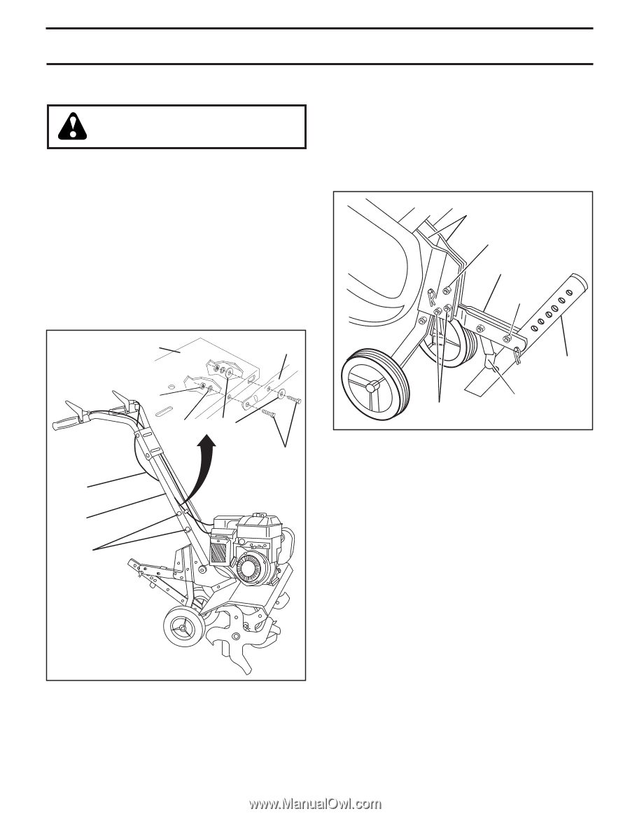
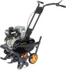
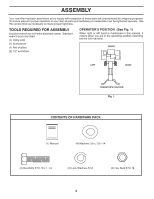
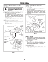
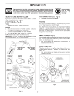
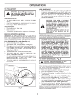
ASSEMBLY UNPACK CARTON & INSTALL HANDLE See Fig. 2) CAUTION: Be careful of exposed staples when handling or disposing of cartoning material. IMPORTANT: WHEN UNPACKING AND ASSEMBLING TILLER, BE CAREFUL NOT TO STRETCH OR KINK CABLE(S). • Cut cable ties securing handles. • The handle may be assembled in high or low posi- tion. Slowly lift handle assembly up, route cable(s) as shown and align handle holes with desired handle panel hole and slot. • Loosely assemble hardware as shown. Repeat for opposite side. Tighten all hardware securely. NOTE: Cables must not touch the muffler. • Cut cable ties securing tiller to skid and remove tiller from skid. • Remove screws securing depth stake to skid and discard the screws. HANDLE PANEL TILLER HANDLE CABLE TILLER HANDLE HANDLE PANEL BOLTS NUT LOCK WASHER FLAT WASHERS HEX BOLTS 5/16-18 x 1-1/4" INSTALL DEPTH STAKE ASSEMBLY (See Fig. 3) • Loosen nut "A". • Insert stake support between engine bracket halves with stake spring down. • Bolt stake support to engine brackets with bolts, lock washers and nuts. Tighten securely. Tighten nut "A". • Depth stake must move freely. If it does not, loosen support bolt. depth_stake_4 ENGINE BRACKET HALVES NUT "A" DEPTH STAKE SUPPORT SUPPORT BOLT DEPTH STAKE STAKE SPRING HEX BOLTS, LOCK WASHERS, AND HEX NUTS Fig. 3 HANDLE HEIGHT • Handle height may be adjusted to better suit operator. (See "HANDLE HEIGHT" in the Service and Adjustments section of this manual). TILLING WIDTH • Tilling width may be adjusted to better handle your tilling conditions (See "TINE ARRANGEMENT" in the Service and Adjustments section of this manual). TINE OPERATION • Check tine operation before first use. (See "TINE OPERATION CHECK" in the Service and Adjustments section of this manual). Fig. 2 5
-
 1
1 -
 2
2 -
 3
3 -
 4
4 -
 5
5 -
 6
6 -
 7
7 -
 8
8 -
 9
9 -
 10
10 -
 11
11 -
12
-
13
-
14
-
15
-
16
-
17
-
18
-
19
-
20
-
21
-
22
-
23
-
24
-
25
-
26
-
27
-
28
-
29
-
30
-
31
-
32
 |
 |