Poulan PRRT850 User Manual - Page 15
Service And Adjustments, Tiller, Engine
 |
View all Poulan PRRT850 manuals
Add to My Manuals
Save this manual to your list of manuals |
Page 15 highlights
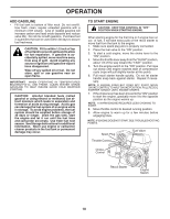
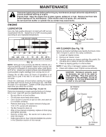
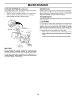
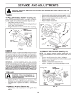
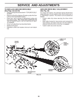
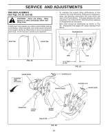
SERVICE AND ADJUSTMENTS CAUTION: Disconnect spark plug wire from spark plug and place wire where it cannot come into contact with plug. TILLER TO ADJUST HANDLE HEIGHT (See Fig. 20) Select handle height best suited for your tilling conditions. Handle height will be different when tiller digs into soil. • First loosen handle lock lever. • Handle can be positioned at different settings between "HIGH" and "LOW" positions. • Retighten handle lock lever securely after adjusting. HANDLE (HIGH POSITION) HANDLE LOCK LEVER • Remove outer side shield by removing nuts "A" and "B". • Remove inner side shield by removing nuts "C" and "D". • Remove hairpin clip and clevis pin from wheel. • Remove wheel and tire. • Repair tire and reassemble. CLEVIS PIN NUT "C" NUT "D" HANDLE (LOW POSITION) FIG. 20 ENGINE Maintenance, repair, or replacement of the emission control devices and systems, which are being done at the customers expense, may be performed by any non-road engine repair establishment or individual. Warranty repairs must be performed by an authorized engine manufacturer's service outlet. IMPORTANT: NEVER TAMPER WITH THE ENGINE GOVERNOR, WHICH IS FACTORY SET FOR PROPER ENGINE SPEED. OVERSPEEDING THE ENGINE ABOVE THE FACTORY HIGH SPEED SETTING CAN BE DANGEROUS. IF YOU THINK THE ENGINE-GOVERNED HIGH SPEED NEEDS ADJUSTING, CONTACT YOUR NEAREST AUTHORIZED SERVICE CENTER/ DEPARTMENT, WHICH HAS THE PROPER EQUIPMENT AND EXPERIENCE TO MAKE ANY NECESSARY ADJUSTMENTS. TIRE CARE CAUTION: When mounting tires, unless beads are seated, overinflation can cause an explosion. • Maintain 20 PSI (1.4 kg/cm2) of tire pressure. If tire pressures are not equal, tiller will pull to one side. • Keep tires free of gasoline or oil which can damage rubber. TO REMOVE WHEEL (See Fig. 21) • Place blocks under transmission to keep tiller from tipping. HAIRPIN CLIP NUT "B" NUT "A" OUTER SIDE SHIELD FIG. 21 tire_4 INNER SIDE SHIELD TO REMOVE BELT GUARD (See Fig. 22) NOTE: For ease of removal, remove hairpin clip and clevis pin from left wheel. Pull wheel out from tiller about 1 inch. • Remove two (2) screws from side of belt guard. • Remove hex nut and washer from bottom of belt guard (located behind wheel). • Pull belt guard out and away from unit. • Replace belt guard by reversing above procedure. BELT GUARD SCREW AND WASHER HEX NUT AND WASHER (LOCATED BEHIND TIRE) SCREW AND WASHER HAIRPIN CLIP AND CLEVIS PIN FIG. 22 15
-
 1
1 -
2
-
3
-
4
-
5
-
6
-
7
-
8
-
9
-
 10
10 -
 11
11 -
 12
12 -
 13
13 -
 14
14 -
 15
15 -
 16
16 -
 17
17 -
 18
18 -
 19
19 -
 20
20 -
21
-
22
-
23
-
24
-
25
-
26
-
27
-
28
-
29
-
30
-
31
-
32
-
33
-
34
-
35
-
36
-
37
-
38
-
39
-
40
-
41
-
42
-
43
-
44
 |
 |
