ProForm 410 Treadmill Trainer English Manual - Page 6
Assembly
 |
View all ProForm 410 Treadmill Trainer manuals
Add to My Manuals
Save this manual to your list of manuals |
Page 6 highlights
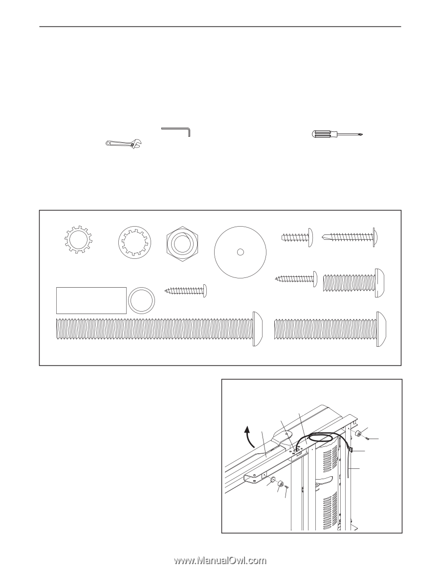
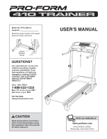
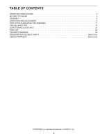
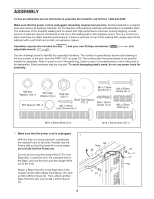
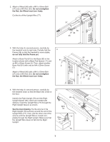
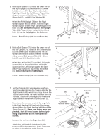
ASSEMBLY To hire an authorized service technician to assemble the treadmill, call toll-free 1-800-445-2480. Make sure that the power cord is unplugged. Assembly requires two persons. Set the treadmill in a cleared area and remove all packing materials. Do not dispose of the packing materials until assembly is completed. Note: The underside of the treadmill walking belt is coated with high-performance lubricant. During shipping, a small amount of lubricant may be transferred to the top of the walking belt or the shipping carton. This is a normal condition and does not affect treadmill performance. If there is lubricant on top of the walking belt, simply wipe off the lubricant with a soft cloth and a mild, non-abrasive cleaner. Assembly requires the included hex key and your own Phillips screwdriver and adjustable wrench . Use the drawings below to identify the assembly hardware. The number in parentheses below each drawing is the key number of the part, from the PART LIST on page 23. The number after the parentheses is the quantity needed for assembly. Note: If a part is not in the parts bag, check to see if it is preattached to one of the parts to be assembled. Extra hardware may be included. To avoid damaging plastic parts, do not use power tools for assembly. M8 Star Washer (10)-4 M10 Star Washer (8)-4 M10 Nut (33)-2 Base Pad Spacer (71)-2 Bolt Spacer (79)-4 M4 x 19mm Latch Screw (A)-2 M4 x 13mm Screw (3)-1 M4 x 19mm Screw (1)-6 M4 x 25mm Screw (2)-4 M8 x 25mm Bolt (6)-4 M10 x 96mm Bolt (5)-4 1. Make sure that the power cord is unplugged. 1 With the help of a second person, carefully tip the treadmill onto its left side. Partially fold the Frame (48) so that the treadmill is more stable; do not fully fold the Frame yet. Cut the tie securing the Upright Wire (77) to the Base (85). Locate the tie in the indicated hole in the Base, and use the tie to pull the Upright Wire out of the hole. Attach a Base Pad (81) to the Base (85) in the location shown with a Base Pad Spacer (71) and an M4 x 25mm Screw (2). Then, attach another Base Pad (81) with only an M4 x 25mm Screw (2). 6 M10 x 50mm Bolt (27)-2 85 Hole 48 71 81 2 81 2 77 Tie
-
 1
1 -
 2
2 -
 3
3 -
 4
4 -
 5
5 -
 6
6 -
 7
7 -
 8
8 -
 9
9 -
 10
10 -
 11
11 -
 12
12 -
13
-
14
-
15
-
16
-
17
-
18
-
19
-
20
-
21
-
22
-
23
-
24
-
25
-
26
-
27
-
28
 |
 |