ProForm 565 Ekg Instruction Manual - Page 6
Maintenance And Troubleshooting
 |
View all ProForm 565 Ekg manuals
Add to My Manuals
Save this manual to your list of manuals |
Page 6 highlights
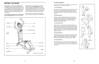
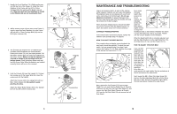
1. Identify the Front Stabiliser (10). Whilst another person lifts the front of the Frame (1), attach the Front Stabiliser to the Frame with two M10 x 75mm Carriage Bolts (34) and two M10 Nylon Locknuts (33). Make sure that the Front Stabiliser is turned so the Wheels (22) are not touching the floor. 1 22 22 10 2. Whilst another person lifts the back of the Frame (1) 2 slightly, attach the Rear Stabiliser (9) to the Frame with two M10 x 75mm Carriage Bolts (34) and two M10 Nylon Locknuts (33). 1 33 34 33 33 1 3. The Console (23) requires four "D" batteries (not included); alkaline batteries are recommended. Remove the screw (72) from the battery drawer. Pull the battery drawer open and insert four batteries into the battery drawer. Make sure that the batteries are oriented as shown by the markings inside the battery drawer. Close the battery drawer and reattach the Screw. Note: When the batteries are installed correctly, the fan will turn on for a moment. 3 Screw 9 34 23 Batteries Battery Drawer 4. Hold the Console (23) near the Upright (2). Connect the console wire to the Upper Wire (44). Insert the excess wire into the Upright. Attach the Console (23) to the Upright (2) with four M4 x 16mm Screws (52). Be careful to avoid pinching the wires. Attach the Water Bottle Holder (63) to the Upright (2) with two M4 x 22mm Screws (42). 4 23 44 Console Wire 2 63 52 42 6 MAINTENANCE AND TROUBLESHOOTING Inspect and properly tighten all parts of the elliptical trainer regularly. Replace any worn parts immediately. The elliptical trainer can be cleaned with a soft cloth and a small amount of mild detergent. Do not use abrasives or solvents. To prevent damage to the console, keep liquids away from the console and keep the console out of direct sunlight. When storing the elliptical trainer, remove the batteries from the console. Keep the elliptical trainer in a clean, dry location, away from moisture and dust. CONSOLE TROUBLESHOOTING If the console does not function properly, replace the batteries (see assembly step 3 on page 6). HOW TO ADJUST THE REED SWITCH If the console does not display correct feedback, the reed switch should be adjusted. To adjust the reed switch, first see assembly step 9 on page 8 and remove the Pedals (13, 14). Next, see step 8 on page 8 and remove the Pedal Arms (11, 12). 64 15 52 4 12 3 64 52 51 52 64 14 64 52 Next, locate the Reed 15 Switch (53). Loosen, but do not remove, the 58 indicated Screw (52). Slide the 53 Reed Switch 52 slightly toward or away from the Magnet (58) on the flywheel. Retighten the Screw. Turn the left Pedal Disc (15) for a moment. Repeat until the console displays correct feedback. When the Reed Switch (53) is correctly adjusted, reattach the Side Shields (3, 4), the right Pedal Disc (15), the Pedal Arms (11, 12), and the Pedals (13, 14). HOW TO ADJUST THE DRIVE BELT If you can feel the pedals slip whilst you are pedaling, even when the resis- tance is adjust- ed to the maxi- 26 mum level, the Drive Belt (19) may need to be adjusted. To 62 19 adjust the Drive Belt, you must remove both side shields. See the instructions at the left and remove the side shields. Next, loosen the M8 x 22mm Flat Head Screw (26) and turn the Idler Adjustment Bolt (62) until the Drive Belt (19) is tight. Once the Drive Belt is tight, tighten the Flat Head Screw. Reattach the side shields. Next, remove the four Screws (51) from the right Pedal Disc (15), and slide the Pedal Disc off. Remove all Screws (52, 64) from the Right Side Shield (4), and remove the Right Side Shield. Remove all Screws (52) from the Left Side Shield (3) and remove the Left Side Shield. 19
-
 1
1 -
 2
2 -
 3
3 -
 4
4 -
 5
5 -
 6
6 -
 7
7 -
 8
8 -
 9
9 -
 10
10 -
 11
11 -
 12
12
 |
 |
