ProForm 738 Bench User Manual - Page 4
Assembly - weight bench
 |
View all ProForm 738 Bench manuals
Add to My Manuals
Save this manual to your list of manuals |
Page 4 highlights
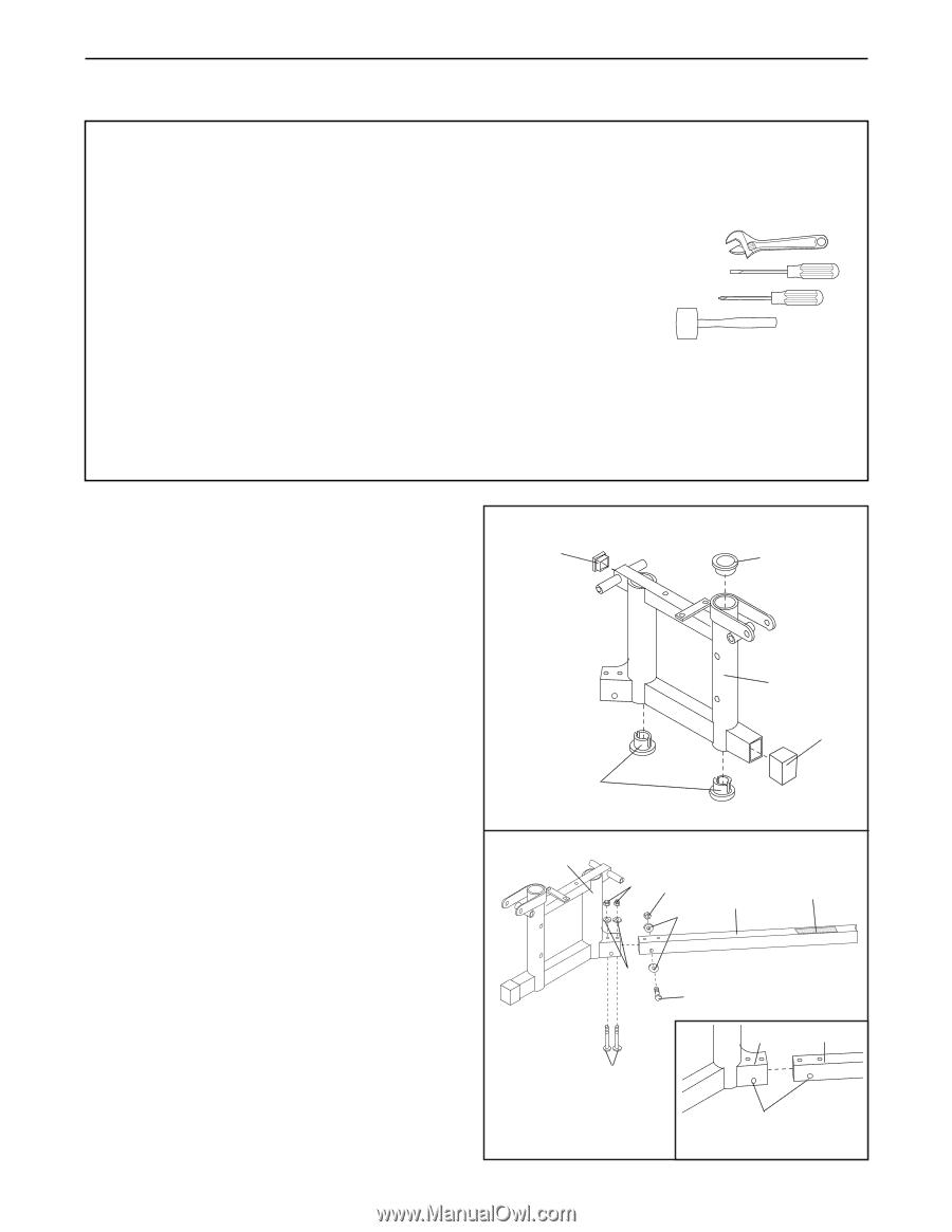
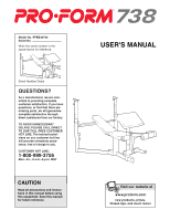
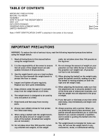
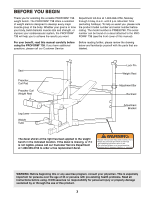
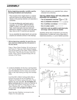
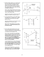
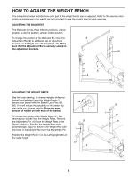
ASSEMBLY Before beginning assembly, carefully read the following information and instructions: ¥ Place all parts of the weight bench in a cleared area and remove the packing materials; do not dispose of the packing materials until assembly is completed. ¥ For help identifying the small parts used in assembly, use the PART IDENTIFICATION CHART located in the center of this manual. Note: Some small parts may have been preattached for shipping. If a part is not in the parts bag, check to see if it has been pre-attached. ¥ As you assemble the weight bench, be sure that all parts are oriented as shown in the drawings. ¥ Tighten all parts as you assemble them, unless instructed to do otherwise. THE FOLLOWING TOOLS (NOT INCLUDED) ARE REQUIRED FOR ASSEMBLY: ¥ Two (2) adjustable wrenches ¥ One (1) standard screwdriver ¥ One (1) phillips screwdriver ¥ One (1) rubber mallet ¥ Lubricant, such as grease or petroleum jelly, and soapy water will also be needed. Assembly will be more convenient if you have the following tools: A socket set, a set of open-end or closed-end wrenches, or a set of ratchet wrenches. 1. Before beginning assembly, be sure that you have read and understand the information in the box above. 1 24 Press a 76mm Plastic Bushing (14) into the top of the Frame (4). Press two 76mm Slotted Endcaps (16) into the bottom of the Frame. Press a 50mm x 70mm Outer Cap (43) onto the lower end of the Frame. Press a 50mm Square Endcap (24) into the back of the Frame. 16 14 4 43 2. Locate the Stabilizer (3) that has a warning decal 2 on it. Turn the Stabilizer so the decal is on top and insert the Stabilizer into the Frame (4) as shown. Refer to the inset drawing and align the indicated holes. Insert two M10 x 85mm Carriage Bolts (25) up through the Frame (4) and the Stabilizer (3). Thread an M10 Nylon Locknut (35) with a 10mm Washer (34) onto each Bolt. Do not tighten the Nylon Locknuts yet. Next, attach the Stabilizer to the Frame with an M10 x 70mm Bolt (31), two 10mm Washers (34), and an M10 Nylon Locknut (35) as shown. Do not tighten the Nylon Locknut yet. Attach the other Stabilizer (not shown) to the Frame (4) in the same way. 4 4 35 35 3 34 Decal 34 25 31 4 3 Align these Holes
-
 1
1 -
 2
2 -
 3
3 -
 4
4 -
 5
5 -
 6
6 -
 7
7 -
 8
8 -
 9
9 -
 10
10 -
11
-
12
-
13
-
14
 |
 |