ProForm C50 English Manual - Page 3
Assembly, Instructions
 |
View all ProForm C50 manuals
Add to My Manuals
Save this manual to your list of manuals |
Page 3 highlights
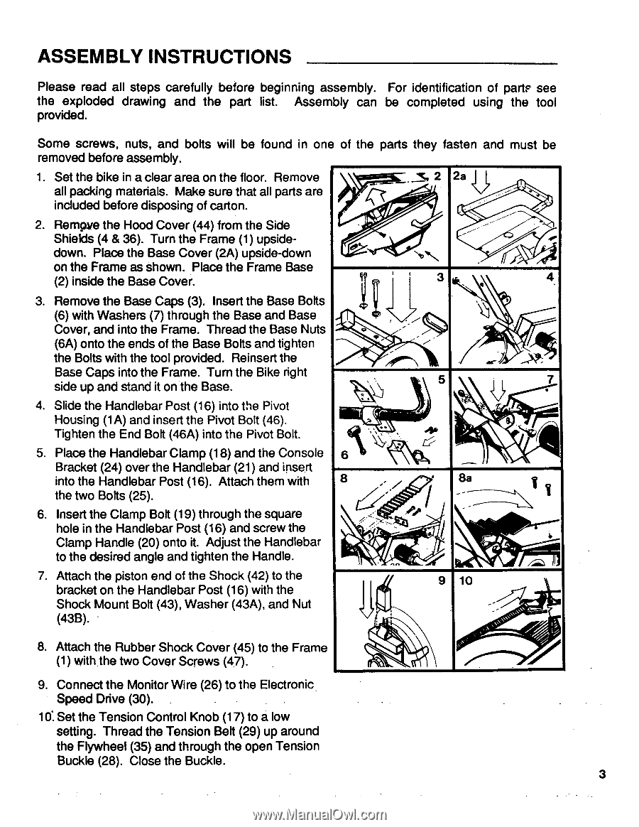
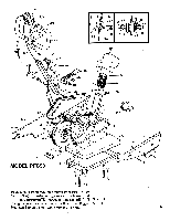
ASSEMBLY INSTRUCTIONS Please read all steps carefully before beginning assembly. For identification of parts see the exploded drawing and the part list. Assembly can be completed using the tool provided. Some screws, nuts, and bolts will be found in one of the parts they fasten and must be removed before assembly. 1. Set the bike in a clear area on the floor. Remove _ _SI 2 2a k . all packing materials. Make sure that all parts are included before disposing of carton. 2. Rempve the Hood Cover (44) from the Side Shields (4 & 36). Turn the Frame (1) upside- down. Place the Base Cover (2A) upside-down 0 17, 414/ ..... on the Frame as shown. Place the Frame Base (2) inside the Base Cover. 3 4 3. Remove the Base Caps (3). Insert the Base Bolts (6) with Washers (7) through the Base and Base Cover, and into the Frame. Thread the Base Nuts (6A) onto the ends of the Base Bolts and tighten the Bolts with the tool provided. Reinsert the Base Caps into the Frame. Turn the Bike right side up and stand it on the Base. 4. Slide the Handlebar Post (16) into the Pivot Housing (1A) and insert the Pivot Bolt (46). Tighten the End Bolt (46A) into the Pivot Bolt. 5. Place the Handlebar Clamp (18) and the Console Bracket (24) over the Handlebar (21) and insert into the Handlebar Post (16). Attach them with the two Bolts (25). 6. Insert the Clamp Bolt (19) through the square hole in the Handlebar Post (16) and screw the Clamp Handle (20) onto it. Adjust the Handlebar to the desired angle and tighten the Handle. 7. Attach the piston end of the Shock (42) to the bracket on the Handlebar Post (16) with the Shock Mount Bolt (43), Washer (43A), and Nut (43B). • N. Mk 6 8 ,-- . _ As- 5 . 7 : - a 8a , 1 Q .---- 4 n ..." 9 10 , - ,,,' ,,s.,„.,.-.i, 8. Attach the Rubber Shock Cover (45) to the Frame (1) with the two Cover Screws (47). 9. Connect the Monitor Wire (26) to the Electronic Speed Drive (30). . 10. Set the Tension Control Knob (17) to a low setting. Thread the Tension Belt (29) up around the Flywheel (35) and through the open Tension Buckle (28). Close the Buckle. 3
-
 1
1 -
 2
2 -
 3
3 -
 4
4 -
 5
5 -
 6
6 -
 7
7 -
 8
8 -
 9
9 -
10
-
11
 |
 |