ProForm C50 English Manual - Page 4
Model
 |
View all ProForm C50 manuals
Add to My Manuals
Save this manual to your list of manuals |
Page 4 highlights
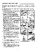
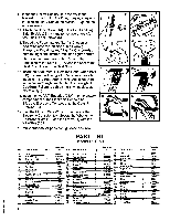
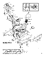
11. Insert the Hollow Bolt (27) into the slot in the bracket on the front of the Pivot Housing (1A) with the nuts on either side of the bracket. Tighten the nuts securely. 12. Attach the Hood Cover (44) to the Right and Le; Side Shields (36 & 4) and to the axle brace w!th the Side Shield Screws (5). 13. Thread the Pedal marked "Left" (10) counterclockwise onto the left side of the Crank (9). Thread the Pedal marked "Right" (37) clockwise onto the right side of the Crank and tighten firmly. 14. Remove the three Seat Nuts (13) from the underside of the Seat (12). Attach the Seat to the Seat Post (11) with the Seat Nuts. 15. Insert the Seat Post (11) into the Rear Frame Post (1B). Screw the T-wingbolt (15) loosely through the hole in the Rear Frame Post. Adjust the Seat to the desired height and tighten the T-wingbolt. Caution: Failure to tighten the T-wingbolt could result in injury. 16. Insert the two "AA" Batteries (23A) into the battery compartment of the Electronic Console (23). Slide the Electronic Console onto the Console Bracket (24). 17. Plug the Monitor Wire (26) into the back of the Electronic Console (23). Secure the Wire to the Handlebar Post (16) and the Frame (1) with the Wire Ties (26A). 18. Make sure that all parts are tightened securely. 11 ..„c, 1, 2 . v.„, 13 14 (© ) .. 15 15a .---- '..- ' Ai )/ . , 16 17 ,,, • • s• dill . , , No. Description Frame 1A Pivot Housing 18 Rear Frame Post 2 Frame Base 2A Base Cover 3 Base Cap 4 Lett side Shield 4A Shield Tab 5 Side Shield Screws 6 Base Bolts 6A Base Nuts 7 Base Lock Washers 8 Seat Post Sleeve 9 Crank Assembly 10 Left Pedal 11 Seat Post 12 Seat 13 Seat Nut 14 Accordion Sleeve 15 T-wingbok Qty. 1 1 1 1 4 1 1 8 .4 4 4 1 1 1 1 1 3 1 1 4 PART LIST Model PFC 50 Reorder No. No. 004063 16 On Frame 17 On Frame 17A 004064 18 040072 19 040034 20 010080 21 008081 22 013086 22A 013074 •23 012003 23A 014001 24 019010 25 023007 26 038005 26A 007006 27 042005 27A 012038 28 010011 29 017003 30 Description Qty. Reorder No. No. Handlebar Post Tension Control Mounting Bolt 2 Handlebar Clamp Clamp Bolt 1 007029 31 072004 32 013017 33 013096 34 013137 35 Clamp Handle 017009 36 Handlebar 1 001011 37 Foam Handgrip 2 041011 38 Handlebar Endcap 2 040040 39 Electronic Console . .1 032006 41 AA Batteries 2 42 Console Bracket 1 008038 43 Bolt 2 013069 43A Monitor Wire . • 1 Adhesive Cable Tie 2 033005 43B 016017 44 Hollow Bolt Spring Assembly 1 013026 45 1oSgeagefee43- 46 Tension Buckle 1 050001 46A Tension Belt 1 Electronic Speed Drive 1 035002 47 033002 48 Description Axle Acorn Nut Axle Washer Chain Flywheel Right Side Shield Right Pedal Sprocket Interior Axle Nut Small Axle Spacer Shock Shock Mount Bolt Washer Nut . Hood Cover Rubber Shock Cover Pivot Bolt End Bolt Cover Screw Cover Plate Qty. 1 2 4 1 1 1 1 1 2 2 2 2 1 1 4 1 Reorder No. 049006 012008 014015 025003 021012 010078 038006 024007 014023 014028 043001 013087 014012 012002 • 009034 010047 049048 013020 013016 008069
-
 1
1 -
 2
2 -
 3
3 -
 4
4 -
 5
5 -
 6
6 -
 7
7 -
 8
8 -
 9
9 -
 10
10 -
11
 |
 |
