ProForm Strideclimber 490 Elliptical English Manual - Page 20
Maintenance And Troubleshooting
 |
View all ProForm Strideclimber 490 Elliptical manuals
Add to My Manuals
Save this manual to your list of manuals |
Page 20 highlights
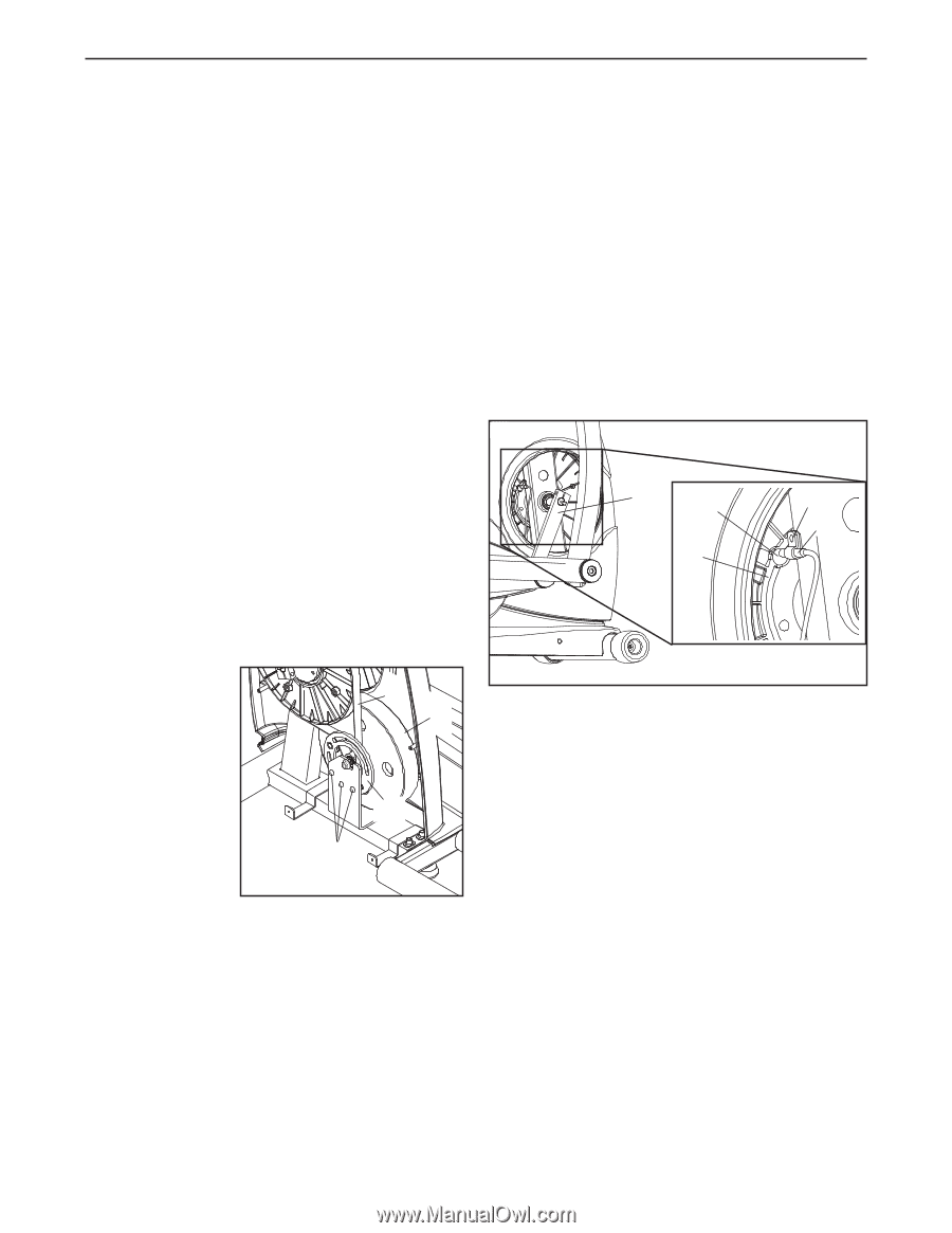
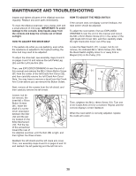
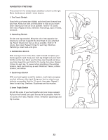
MAINTENANCE AND TROUBLESHOOTING Inspect and tighten all parts of the elliptical exerciser regularly. Replace any worn parts immediately. To clean the elliptical exerciser, use a damp cloth and a small amount of mild soap. IMPORTANT: To avoid damage to the console, keep liquids away from the console and keep the console out of direct sunlight. HOW TO ADJUST THE DRIVE BELT HOW TO ADJUST THE REED SWITCH If the console does not display correct feedback, the reed switch should be adjusted. To adjust the reed switch, first see EXPLODED DRAWING A near the end of this manual and loosen the M6 x 25mm Button Screw (61) in the center of the right Crank Arm Cover (32), and then carefully rotate the right Crank Arm Cover out of the way. If the pedals slip while you are pedaling, even while the resistance is adjusted to the highest setting, the drive belt may need to be adjusted. To adjust the drive belt, see assembly steps 8 and 9 on pages 9 and 10 and remove the Left Pedal Leg (24) and the Left Link Arm (25). Locate the Reed Switch (21). Loosen, but do not remove, the indicated M4 x 16mm Screw (72). Slide the Reed Switch slightly closer to or away from a Magnet (18) on the Pulley (13). Then, see EXPLODED DRAWING A near the end of this manual and remove the M6 x 25mm Button Screw (61) from the center of the left Crank Arm Cover (32), and then carefully remove the left Crank Arm Cover. Note: You may have to remove a decal from the Crank Arm Cover before you can remove the Button Screw. 31 18 72 21 13 Next, remove all the screws from the left shield, and then carefully remove the left shield. Loosen, but do not remove, the three M6 x 25mm Button Screws 68 10 (61). Insert the shaft of a screw- driver downward between the Idler (12) and the pul- 12 ley located on the Eddy Mechanism 61 (10). Pull the top of the screwdriver toward the rear of the elliptical exerciser until the Belt (68) is tight, and then tighten the three screws. Then, retighten the M4 x 16mm Screw (72). Turn one of the Crank Arms (31) for a moment. Repeat until the console displays correct feedback. When the reed switch is correctly adjusted, replace the crank arm cover. Reattach the left shield and the left crank arm cover. Then, see assembly steps 8 and 9 on pages 9 and 10 and reattach the left pedal leg and the left link arm. 20
-
 1
1 -
2
-
3
-
4
-
5
-
6
-
7
-
8
-
9
-
10
-
11
-
12
-
13
-
14
-
 15
15 -
 16
16 -
 17
17 -
 18
18 -
 19
19 -
 20
20 -
 21
21 -
 22
22 -
 23
23 -
 24
24 -
 25
25 -
26
-
27
-
28
 |
 |