RCA EZDVD1BD User Manual - EZDVD2BD - Page 4
Connections - memory maker
 |
View all RCA EZDVD1BD manuals
Add to My Manuals
Save this manual to your list of manuals |
Page 4 highlights
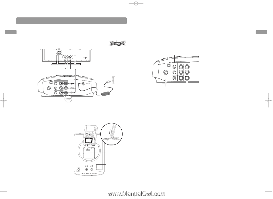
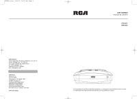
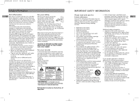
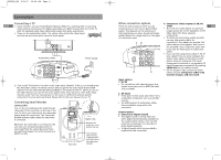
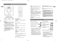
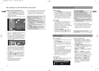
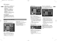
EZDVD1_EN 8/9/07 10:08 AM Page 6 Connections Connecting a TV EN 1. If you intend to use your Small Wonder Memory Maker for watching DVD or recording other external sources (e.g. TV, digital camcorder), you MUST connect the unit to the TV with the supplied audio video cables (color-coded red, white and yellow). • These are the audio/video cables. The yellow cable carries the video signal, and the red and white cables carry the audio signal. Audio/video cables DV IN INPUT OUTPUT RR Pr LL Pb COAXIAL VIDEO VIDEO Y OUT Power supply DC 12V 2. Turn on the TV and tune it to the correct Video Input Channel. To do so, you usually press the AV button on the TV remote control until you get to the video input channel that matches how the Small Wonder Memory Maker is connected to the TV. When you are on the right channel, you can see the unit's player menu. Since access to a TV's video input channel varies from one manufacturer to the next, it is difficult to provide specific instructions for your particular brand. Please refer to the user manual of your TV. Connecting Small Wonder camcorder Turn on the unit and place the Small Wonder camcorder to the connector on the top of the unit. To do so, you have to put the camcorder upside down for connection. The Camcorder Docked indicator lights when the camcorder is connected. Whenever the camcorder is connected to the unit, the unit will automatically switch to view input from the camcorder even if you are watching images from other sources (e.g. INPUT1 or DV). Top view Right view Remove the protective cover before first use This indicator blinks during communication and lights when the camcorder docked 6 Other connection options There are several ways in which you can incorporate your unit into an Audio-Video system. This depends on the sockets and other appliances you have. Sound and image quality depend to a large extent on the types of connections used. 12 DV IN INPUT OUTPUT RR Pr LL Pb COAXIAL VIDEO VIDEO Y OUT 3 4 4. Component video outputs (Y, Pb, Pr) (YUV) EN • The Y, Pb, Pr sockets deliver an optimum image quality due to the separation of the video signal into three separate components. • To obtain the best image quality possible, use very high quality cables for connections. Your dealer can provide YUV cables that are sold together and come in the standard colour codes (red, green and blue) used for these types of sockets and cables. • If you use the Component sockets Y, Pb, Pr (also called YUV), you must configure the output video signal so that these sockets deliver either an interlaced YUV signal (component interlaced) or a progressive PS signal (component progressive) by pressing VIDEO OUT on the remote control. • Do not forget to also connect the audio cables, because Component cables only transmit images, and not sound. Input options 1. DV IN • For connection with external source (e.g digital camcorder) with an IEEE1394 cable (not provided). 2. AV input • These jacks receive audio and video from a compatible component, such as a satellite receiver. • An additional set of audio/video cables (not provided) is required for this connection. Output options 3. Coaxial out (digital sound) • The digital sound of a DVD video disc when played is permanently available on the coaxial socket of your unit. Use this socket by connecting it to a decoder or Dolby Digital amplifier. • A digital coaxial cable (not provided) is required for this connection. 7
-
 1
1 -
 2
2 -
 3
3 -
 4
4 -
 5
5 -
 6
6 -
 7
7 -
 8
8 -
 9
9 -
 10
10 -
11
-
12
 |
 |