RCA MGWHTR Installation Manual - Page 4
Step 1
 |
View all RCA MGWHTR manuals
Add to My Manuals
Save this manual to your list of manuals |
Page 4 highlights
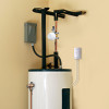
STEP 1 (continued) C. Mount the control unit to wall The control unit offers three options for mounting to the wall. Option 1: Double-sided tape (included, not for masonry applications) 1. Clean the wall where you want to mount the unit. 2. Apply the double-sided sticky tape to the back of the control unit. 3. Peel off the exposed side of the sticky tape. 4. Press the control unit firmly against the wall where you want to mount it. Option 2: Drywall screws with anchors (included) 1. Place the mounting template on the wall where you want to mount the control unit. IMPORTANT: Make sure there are no electrical wires where you plan to drill. 2. Draw x's on the wall where indicated by the mounting template. Drill a 1/4" pilot hole at each x for the anchors. Tap in gently as needed. 3. Install the dry-wall anchors at the marked location with a #2 Phillips screwdriver 4. Mount the drywall screws in the anchors. Leave some space between the screw heads and the wall so that you can mount the control unit on the screws. 5. Mount the control unit on the screws. Mounting template MOUNTING TEMPLATE FOR THE CONTROL UNIT 45mm(1.77") USE FOR FLAT WALL MOUNT ONLY Drywall screws 72mm(2.83") Option 3: Masonry screws (included) 1. Place the mounting template on the wall where you want to mount the control unit. 2. Draw x's on the wall where indicated by the mounting template. Masonry screws 3. Use a 5/32" masonry drill bit to drill pilot holes where you marked the x's. The holes should be about 1-1/2" deep. 4. Mount the masonry screws where you drilled the pilot holes. Leave some space between the screw heads and the wall so that you can mount the control unit on the screws. 5. Mount the control unit on the screws. 4
-
 1
1 -
 2
2 -
 3
3 -
 4
4 -
 5
5 -
 6
6 -
 7
7 -
 8
8 -
 9
9 -
 10
10 -
11
-
12
-
13
-
14
-
15
-
16
 |
 |
