Ridgid OL50145MWD Operation Manual - Page 10
Assembly - compressor
 |
View all Ridgid OL50145MWD manuals
Add to My Manuals
Save this manual to your list of manuals |
Page 10 highlights
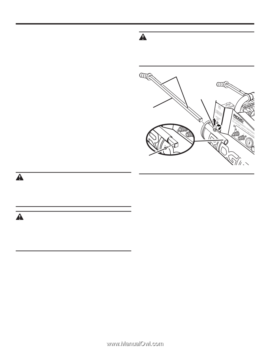
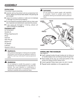
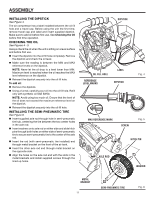
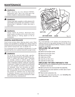
ASSEMBLY UNPACKING This product requires assembly. Carefully remove the product and any accessories from the box. Make sure that all items listed in the packing list are included. Inspect the product carefully to make sure no breakage or damage occurred during shipping. Do not discard the packing material until you have carefully inspected and satisfactorily operated the product. If any parts are damaged or missing, please call 1-800-4-RIDGID for assistance. PACKING LIST Air Compressor Handles (2) Phillips Head Screw (4) Wheel Axle Rod Hitch Pins (2) Washers (2) Oil Dipstick Lubricant Operator's Manual WARNING: If any parts are damaged or missing do not operate this product until the parts are replaced. Failure to heed this warning could result in serious personal injury. WARNING: Do not attempt to modify this product or create accessories not recommended for use with this product. Any such alteration or modification is misuse and could result in a hazardous condition leading to possible serious personal injury. WARNING: Do not connect to power supply until assembly is complete. Failure to comply could result in accidental starting and possible serious personal injury. hOLES handle screw HANDLE RELEASE KNOB 0041,1,.41242959m,Sm99M399C/3M/MKFbai1apM5ni1xn8rA8@,G7@,P8@La6SL6i,lti22ltr9Iroo11e0nbkPPaSraI ON OFF I O 1 2 OMILILNUIBWE HPUEMELPB-APORMRPEOAWHULEC-NOBCOHMMUFBPEA RC-OTENASLNUSBROICRACITOMN 4 6 DE ACIETE 80 2 40 120 0 bar 160 E T ANQUE - TANK 4 6 80 2 40 120 0 bar 160 Fig. 3 installing the HANDLES See Figure 3. Insert supplied handle through handle slot by lifting up on handle release knob and sliding handle through slot. Push handle all the way up to the bent portion of the handle and release handle release knob. Install supplied Phillips head screw into slot in handle. Repeat handle installation on the opposite side. - RESEVIOR K - SORTIE 10
-
 1
1 -
2
-
3
-
4
-
 5
5 -
 6
6 -
 7
7 -
 8
8 -
 9
9 -
 10
10 -
 11
11 -
 12
12 -
 13
13 -
 14
14 -
 15
15 -
16
-
17
-
18
-
19
-
20
 |
 |