Ridgid OL50145MWD Operation Manual - Page 11
Installing The Dipstick, Checking The Oil, Installing The Semi-pneumatic Tire
 |
View all Ridgid OL50145MWD manuals
Add to My Manuals
Save this manual to your list of manuals |
Page 11 highlights
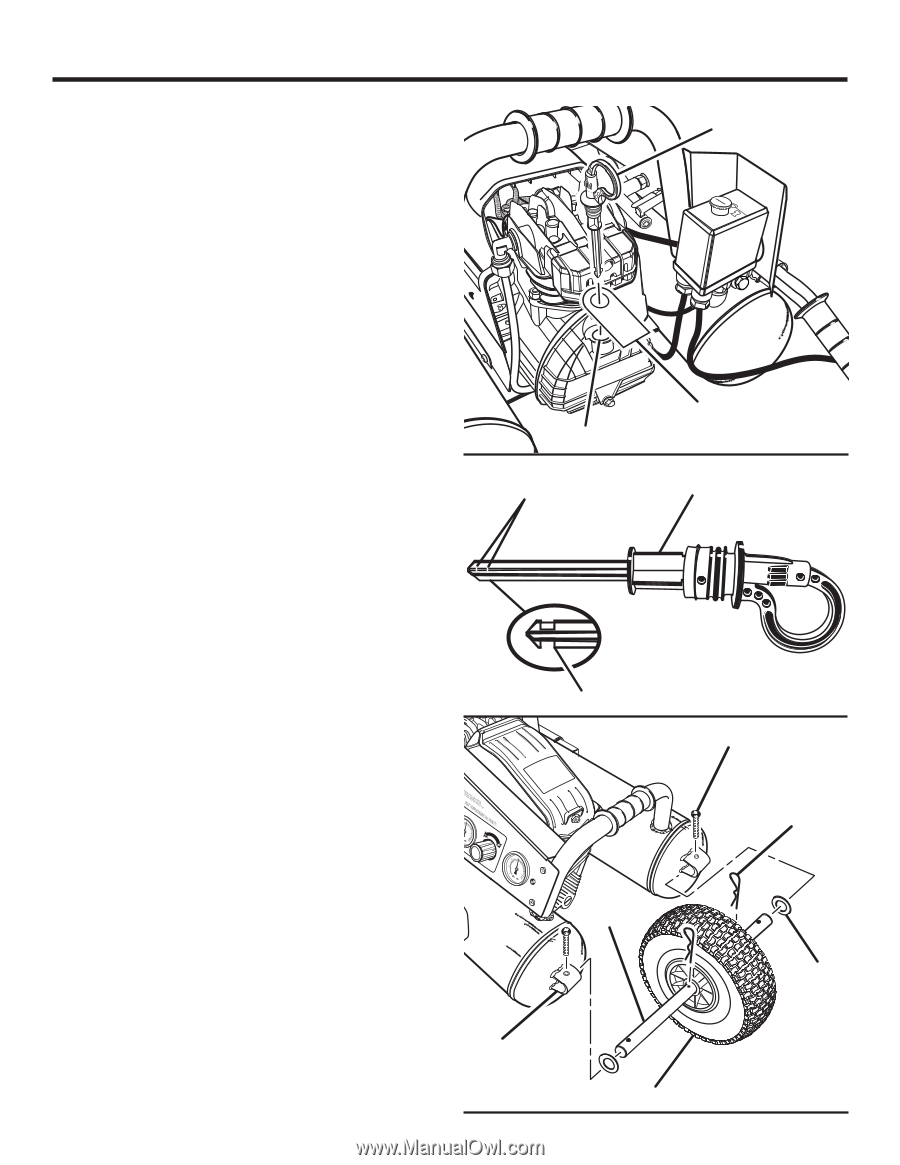
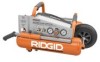
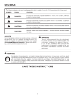
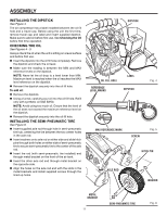
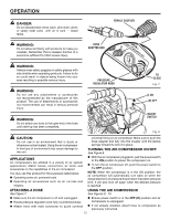
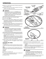
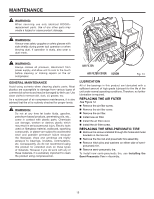
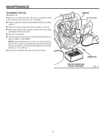
ASSEMBLY installing the dipstick See Figure 4. dipstick The air compressor has a label installed between the oil fill hole and a travel cap. Before using the unit the first time, remove travel cap and label and insert supplied dipstick. Make sure to add oil before first use. See Checking the Oil ON OFF I O ON before first time operation. checking the oil See Figures 4 - 5. ADaDddOoIiLl aBnADEdPÉaFiPMnaApOODsbpBARedaIoEANRrE'sithnSATRtdutSeTRAiidDcpTleE'GResA'hHCtrpERAuicrUdEi.TNkelaeeIR.RmnLCbReeateEiDAeetteefiosrirRPmEinetrdeRdesLorAééevOEbysmCretoMea.aiaEnucrrRrIrrtcatIEjraraTehapuoRnutEo,gpdicgrn.eueaAe,.zrNlclaoaT.tEalapSata,pa, Always check the oil when the unit is sitting on a level surface and before first use. n Insert the dipstick into the oil fill hole completely. Remove the dipstick and check the oil level. n Make sure the reading is between the MIN and MAX reference levels on the dipstick. NOTE: Never let the oil drop to a level lower than MIN. Maximum level is reached when the oil reaches the MAX level reference on the dipstick. oil fill hole label Fig. 4 n Reinsert the dipstick securely into the oil fill hole. To add oil: n Remove the dipstick. reference level marks dipstick n Using a funnel, carefully pour oil into the oil fill hole. Refill only with synthetic oil SAE 5W50. NOTE: Avoid using too much oil. Ensure that the level of the oil does not exceed the maximum reference level on the dipstick. n Reinsert the dipstick securely into the oil fill hole. MAX installing the SEMI-PNEUMATIC TIRE See Figure 6. Insert supplied axle rod through hole in semi-pneumatic ON OFF I O tiIptrnniiorrisneedtesh.throettuhswabreox,aclucseugehrrhneeotrbdsesoe.roimtnnhgit-hoptohanleexesluteimorrenoabdetieicotthnwtiereeeriestthnoidetterhhsoeeifdctsweeenoamtnecid-reposnnlftieedthureemhhoaiatxlctelihecs 0041,1,.41242959m,Sm99M399C/3M/MKFbai1apM5ni1xn8rA8@,G7@,P8@La6SL6i,lti22ltr9Iroo11e0nbkPPaSraI OMILILNUIBWE HPU1EMELPB-APORMRP2EOAWHULEC-NOBCOHMMUFBPEA RC-OTENASLNUSBROICRACITOMN 4 6 Insert tire rod (with semi-pneumatic tire installed) end 80 2 40 120 DE ACIETE 0 bar 160 max reference mark E T - RESEVIOR K - SORTIE through metal bracket on the front of the air tank. ANQUE - TANK 4 6 Insert the other axle rod end through metal bracket on 80 2 40 120 0 bar 160 the opposite side. SCREW Fig. 5 HITCH PIN Align the holes on the axle rod end with the slots in the metal brackets and install supplied screws through the lined up holes. AXLE ROD WASHER METAL BRACKET 11 SEMI-PNEUMATIC TIRE Fig. 6
-
 1
1 -
2
-
3
-
4
-
5
-
 6
6 -
 7
7 -
 8
8 -
 9
9 -
 10
10 -
 11
11 -
 12
12 -
 13
13 -
 14
14 -
 15
15 -
 16
16 -
17
-
18
-
19
-
20
 |
 |