Ryobi A25RT03 Operation Manual - Page 10
Assembling The Router Table, Attaching The Switch Box, Attaching The Under Table Guards, Attaching
 |
View all Ryobi A25RT03 manuals
Add to My Manuals
Save this manual to your list of manuals |
Page 10 highlights
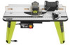
ASSEMBLY ASSEMBLING THE ROUTER TABLE Assembling the router table involves attaching the switch box, the under table guards, the legs, the router/insert plate assembly, the fence assembly, featherboard, throat plate, starting pin, and installing the miter gauge to the router table. ATTACHING THE SWITCH BOX See Figure 5. The switch box will come with the screws and nuts attached. Use these screws and nuts to attach the switch box to the table. Loosen and remove the screws and nuts from the switch box. Place the router table upside down on a flat surface. Hold the switch box so that the words ON and OFF on the toggle switch are upside down. Line up the three holes in the switch box with the three holes on the outside of the front rail, this is the rail that is already installed on the front underside of the router table. Insert the switch box screws through the holes in the switch box and through the holes in the front rail. Install the nuts on the back of the switch box screws. Holding the screws in place with a screwdriver, tighten the nuts onto the screws with a wrench or socket. ATTACHING THE UNDER TABLE GUARDS See Figure 6. Remove the under table guard screws from the blister pack. Use these screws to attach the under table guards. Place the router table upside down on a flat surface. Position the under table guards in front of and behind the insert plate area. The front under table guard should have the open ended side facing the back of the router table. Align the three holes of the under table guards with the holes in the table. The front under table guard will be bolted through the front rail and in to the table. Insert the under table guard screws through the holes and into the table. Tighten screws with a screwdriver. ATTACHING THE TABLE LEGS See Figure 7. Remove the table leg screws from the blister pack. Use these screws to attach the table legs. Place router table upside down on a flat, level surface with the front edge closest to you. Place each leg in a corner of the table. The legs with the warning labels should go in the front, and the legs without the warning labels should go in the back. SWITCH KEY SWITCH BOX SWITCH BOX NUT SWITCH BOX SCREW UNDER TABLE GUARDS FRONT RAIL Fig. 5 UNDER TABLE GUARD SCREW FRONT RAIL TABLE LEG TABLE LEG SCREW Fig. 6 FRONT SIDE RIGHT LEG- FRENCH / SPANISH LABEL LEFT LEG- ENGLISH LABEL Fig. 7 10 - English
-
 1
1 -
2
-
3
-
4
-
 5
5 -
 6
6 -
 7
7 -
 8
8 -
 9
9 -
 10
10 -
 11
11 -
 12
12 -
 13
13 -
 14
14 -
 15
15 -
16
-
17
-
18
-
19
-
20
-
21
-
22
-
23
-
24
-
25
-
26
-
27
-
28
-
29
-
30
-
31
-
32
-
33
-
34
-
35
-
36
-
37
-
38
-
39
-
40
-
41
-
42
-
43
-
44
-
45
-
46
-
47
-
48
-
49
-
50
-
51
-
52
-
53
-
54
-
55
-
56
 |
 |
