Ryobi A25RT03 Operation Manual - Page 11
Pre-drilling Holes For Through Table, Depth Adjustment, Attaching The Router To The Table, Attaching
 |
View all Ryobi A25RT03 manuals
Add to My Manuals
Save this manual to your list of manuals |
Page 11 highlights
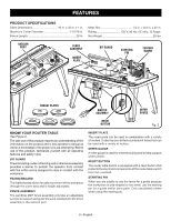
ASSEMBLY NOTE: The table leg with the English language warning should go next to the switch box. Align the four holes in the legs with the four corresponding threaded holes in the table. Insert the table leg screws through the holes and into the table. Tighten screws with a screwdriver. PRE-DRILLING HOLES FOR THROUGH TABLE DEPTH ADJUSTMENT See Figure 8. Since each router will have different placements for through table depth adjustments, pilot holes have been pre-drilled in the throat plate to assist in through table adjustments. Only the models listed below in the key are available for use with the through table depth adjustment feature. n Remove the throat plate. n Determine which router you have and find the pre-drilled pilot hole that matches your router. (Refer to the key below.) n Using a drill and drill bit, drill a hole through the pilot hole large enough for the depth adjustment tool (not included with router table, but may be included with your router) to pass though so through table depth adjustments can be made. Figure 8 Key: RD: RIDGID R2930, R22002 RY: Ryobi R163K, R163GK ML: Milwaukee 5615-20, 5616-20 PC1: Porter-Cable 890 Series PC2: Porter-Cable 8529 PRE-DRILLED PILOT HOLES RD INSERT PLATE REAR SIDE ML NOTCH PC2 RY PC1 PC1 Fig. 8 INSERT PLATE FRONT SIDE A1 B4 NOTCH H A2 A6 B1 A5 B2 B3 A3 A4 Fig. 9 ROUTER INSERT PLATE SCREWS ATTACHING THE ROUTER TO THE TABLE For ease of use, assemble the router to the insert plate with the insert plate removed first, then install the insert plate/ router assembly into the router table. INSERT PLATE ATTACHING THE ROUTER TO THE INSERT PLATE See Figures 9 - 10. Remove the router insert plate screws from the blister pack. Use these screws to attach the router insert plate. n Unplug the router table and/or the router. n Remove the insert plate. n Remove the subbase plate from the router. n Using the following chart for reference, and using one of the three included sets of three router insert plate screws, attach the router to the insert plate with the pilot holes facing the router and the notch in the insert plate facing the back of the router table. NOTE: When attaching insert plate to the router, make sure the holes in the router base match up with the insert plate accurately and are not off-center. 0 1 Inch 3 2 1 INSERT PLATE SCREWS Fig. 10 NOTCH DIFREEECDTION 3 2 1 0 1 Fig. Inch 11 11 - English
-
 1
1 -
2
-
3
-
4
-
5
-
 6
6 -
 7
7 -
 8
8 -
 9
9 -
 10
10 -
 11
11 -
 12
12 -
 13
13 -
 14
14 -
 15
15 -
 16
16 -
17
-
18
-
19
-
20
-
21
-
22
-
23
-
24
-
25
-
26
-
27
-
28
-
29
-
30
-
31
-
32
-
33
-
34
-
35
-
36
-
37
-
38
-
39
-
40
-
41
-
42
-
43
-
44
-
45
-
46
-
47
-
48
-
49
-
50
-
51
-
52
-
53
-
54
-
55
-
56
 |
 |
