Ryobi P610 English Manual - Page 12
Warning, Starting/stopping The Planer, Kickstand, Planing Depth
 |
View all Ryobi P610 manuals
Add to My Manuals
Save this manual to your list of manuals |
Page 12 highlights
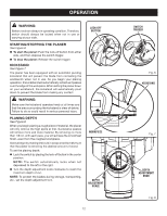
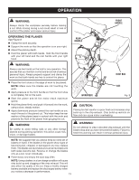
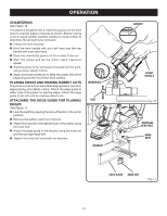
OPERATION WARNING: Battery tools are always in operating condition. Therefore, switch should always be locked when not in use or carrying at your side. STARTING/STOPPING THE PLANER See Figure 6. To start the planer: Push the lock-off button from either side, and then depress the switch trigger. To stop the planer: Release the switch trigger. KICKSTAND See Figure 7. The planer has been equipped with an automatic pivoting kickstand that will prevent the blade from contacting the workbench when not in use. As you begin your planing operation, the kickstand will automatically retract as it passes over the edge of the workpiece. When setting the planer down on your workbench, the kickstand will automatically pivot down to prevent the blade from making any contact. WARNING: Make sure the kickstand operates freely at all times and that the area surrounding the kickstand is clear of debris. Failure to do so could result in serious personal injury. PLANING DEPTH See Figure 8. When you begin planing a rough piece of material, the planer will only remove the high spots at first. Successive passes will remove more and more material. By removing no more than 1/64 in. with each pass, you will achieve the smoothest finish, even from the roughest workpiece. Always begin by making test cuts in scrap wood to make sure that the planer is removing the desired amount of wood. To set the planing depth: Lock the switch by placing the lock-off button in the center position. NOTE: The switch automatically locks when not depressed to the left or the right. Turn the depth adjustment knob clockwise to reach the maximum depth of cut. NOTE: To protect the blades during storage, transporting, etc., set the depth adjustment to 0. LOCK-OFF BUTTON WORKPIECE DEPTH ADJUSTMENT SCALE 12 (01.464mm) SWITCH TRIGGER Fig. 6 KICKSTAND Fig. 7 DEPTH ADJUSTMENT KNOB Fig. 8
-
 1
1 -
2
-
3
-
4
-
5
-
6
-
 7
7 -
 8
8 -
 9
9 -
 10
10 -
 11
11 -
 12
12 -
 13
13 -
 14
14 -
 15
15 -
 16
16 -
 17
17 -
18
-
19
-
20
 |
 |
