Ryobi RE180PL1G Operation Manual
Ryobi RE180PL1G Manual
 |
View all Ryobi RE180PL1G manuals
Add to My Manuals
Save this manual to your list of manuals |
Ryobi RE180PL1G manual content summary:
- Ryobi RE180PL1G | Operation Manual - Page 1
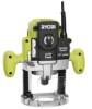
OPERATOR'S MANUAL PLUNGE BASE ROUTER VARIABLE SPEED DOUBLE INSULATED RE180PL1 Your router has been engineered and manufactured to our high standard for dependability, ease of operation, and operator safety. When properly cared for, it will give you years of rugged, trouble-free performance. WARNING: - Ryobi RE180PL1G | Operation Manual - Page 2
in workmanship or materials in your RYOBI® power tool for a period of two years from the date of purchase. With the exception of batteries, power tool accessories are warranted for ninety (90) days. Batteries are warranted for two years. HOW TO GET SERVICE: Just return the power tool, properly - Ryobi RE180PL1G | Operation Manual - Page 3
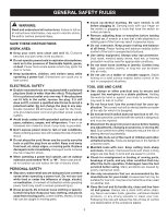
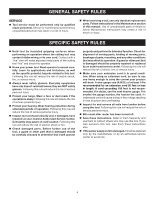
of moving parts, breakage of parts, and any other condition that may affect the tool's operation. If damaged, have the tool serviced before using. Many accidents are caused by poorly maintained tools. Use only accessories that are recommended by the manufacturer for your model. Accessories that - Ryobi RE180PL1G | Operation Manual - Page 4
servicing a tool, use only identical replacement parts. Follow instructions in the Maintenance section of this manual. Use of unauthorized parts or failure to follow Maintenance Instructions router has been turned off. Save these instructions. Refer to them frequently and use them to instruct - Ryobi RE180PL1G | Operation Manual - Page 5
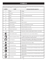
Revolutions, strokes, surface speed, orbits etc., per minute Wet Conditions Alert Do not expose to rain or use in damp locations. Read The Operator's Manual Eye Protection Safety Alert No Hands Symbol No Hands Symbol No Hands Symbol No Hands Symbol Hot Surface To reduce the risk of injury, user - Ryobi RE180PL1G | Operation Manual - Page 6
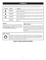
parts. WARNING: To avoid serious personal injury, do not attempt to use this product until you read thoroughly and understand completely the operator's manual. If you do not understand the warnings and instructions in the operator's manual, do not use this product. Call Ryobi customer service - Ryobi RE180PL1G | Operation Manual - Page 7
service technician. For service, we suggest you return the tool to your nearest authorized service center for repair. Always use original factory replacement parts when servicing round jacketed cords listed by Underwriter's **Ampere rating (on tool data plate) 0-2.0 2.1-3.4 3.5-5.0 5.1-7.0 7.1-12.0 - Ryobi RE180PL1G | Operation Manual - Page 8
FEATURES PRODUCT SPECIFICATIONS Plunge Depth 2 in. Collet 1/2 in. Adaptor 1/4 in. Horsepower 2 No Load Speed 15,000-23,000 r/min. (RPM) Input 120 V, 60 Hz, AC only, 10 Amps Net - Ryobi RE180PL1G | Operation Manual - Page 9
Stop located on the base of your router provides precise stops for accessories from the box. Make sure that all items listed in the packing list LIST Plunge Router 1/4 in. Adaptor Wrench Screws (2) Operator's Manual WARNING: If any parts are damaged or missing do not operate this tool until the parts - Ryobi RE180PL1G | Operation Manual - Page 10
attachments or accessories not recommended can result in serious personal injury. APPLICATIONS You may use this tool for the purposes listed below: To remove the adaptor: Place the wrench provided through front of router base onto collet nut and turn counterclockwise to loosen. Loosen the collet - Ryobi RE180PL1G | Operation Manual - Page 11
shield. To remove the bit: Place the wrench provided through front of router base onto collet nut and turn counterclockwise to loosen. Loosen the collet nut COLLET NUT WRENCH BIT Fig. 3 TO UNLOCK HEX NUTS PLUNGE LOCK LEVER SCALE BIT INSIDE SUBBASE Fig. 4 LOCK KNOB STOP BAR TIP OF BIT TOUCHING - Ryobi RE180PL1G | Operation Manual - Page 12
™ Micro-Adjustable Depth Stop is located on the base of your router and makes it possible to make deep or heavy cuts in successive passes. Alignment marks make depth of cut changes quick and easy. A preset cutting depth is achieved by plunging router until stop bar comes in contact with depth stop - Ryobi RE180PL1G | Operation Manual - Page 13
bit by unlocking plunge lock lever. Place router on flat surface, and lower router until tip of bit barely touches flat surface. Lock plunge lock lever to be active. The speed selection chart shown gives suggested speed settings based on the diameter of the bit and the type of material being - Ryobi RE180PL1G | Operation Manual - Page 14
across a workpiece, clamp a straight edge to the workpiece to use as a guide. Position the straight edge parallel to the line of cut and offset the distance between the cutting edge of the bit and the edge of the router base. Hold the router base against the straight edge and rout the groove. When - Ryobi RE180PL1G | Operation Manual - Page 15
of cut (as adjusted by router depth setting) are such that only the top part of the edge is to be shaped (leaving edge), the bit will make less than a full cut - which will alter the shape of the finished edge. WORK ROUTER Fig. 13 TOP EDGE SHAPING PILOT ROUTER WORK GUIDE PILOT WHOLE EDGE - Ryobi RE180PL1G | Operation Manual - Page 16
firmly and surely to produce a continuous spiral of uniform chips or a smooth edge. Listen to the sound of the motor. A high-pitched sound means you feed rate may be determined by the speed at which you can travel the router along the guide line. If the bit is a large one, the cut is deep, - Ryobi RE180PL1G | Operation Manual - Page 17
edge shaping can be done only when the bit is revolving at a relatively high speed and is taking very small bites to produce tiny, cleanly severed chips. If you force the router Also, because bigger bites require more power, the router motor may become overloaded. Under extreme force-feeding - Ryobi RE180PL1G | Operation Manual - Page 18
difficult to guide and control router to the router table properly. Use of any other type and size screws could result in an accident causing possible serious injury. Do not use 8 mm screws. DEPTH OF CUT WIDTH OF CUT 2ND PASS 1ST PASS 2ND PASS 1ST PASS Fig. 19 Fig. 20 ADJUSTMENTS PLUNGE - Ryobi RE180PL1G | Operation Manual - Page 19
servicing, use only identical replacement parts. Use of any other parts When sharpening bits, sharpen only the inside of the cutting edge. Never grind the outside diameter. When sharpening the end of for wear. To replace brushes: Unplug the router. Remove brush cap with a screwdriver. Brush - Ryobi RE180PL1G | Operation Manual - Page 20
will be found on a plate attached to the motor housing. Please record the model number and serial number in the space provided below. • HOW TO ORDER REPAIR PARTS When ordering repair parts, always give the following information: • MODEL NUMBER RE180PL1 • SERIAL NUMBER Ryobi® is a registered
-
 1
1 -
 2
2 -
 3
3 -
 4
4 -
 5
5 -
 6
6 -
 7
7 -
8
-
9
-
10
-
11
-
12
-
13
-
14
-
15
-
16
-
17
-
18
-
19
-
20
 |
 |

SAVE THIS MANUAL FOR FUTURE REFERENCE
Your router has been engineered and manufactured to our high standard for dependability, ease of operation, and operator
safety. When p
roperly cared for, it will give you years of rugged, trouble-free performance.
WARNING:
To reduce the risk of injury, the user must read and understand the operator’s manual before using
this product.
Thank you for your purchase.
OPERATOR’S MANUAL
PLUNGE BASE ROUTER
VARIABLE SPEED
DOUBLE INSULATED
RE180PL1