Ryobi RE180PL1G Operation Manual - Page 13
Speed Selection Chart
 |
View all Ryobi RE180PL1G manuals
Add to My Manuals
Save this manual to your list of manuals |
Page 13 highlights
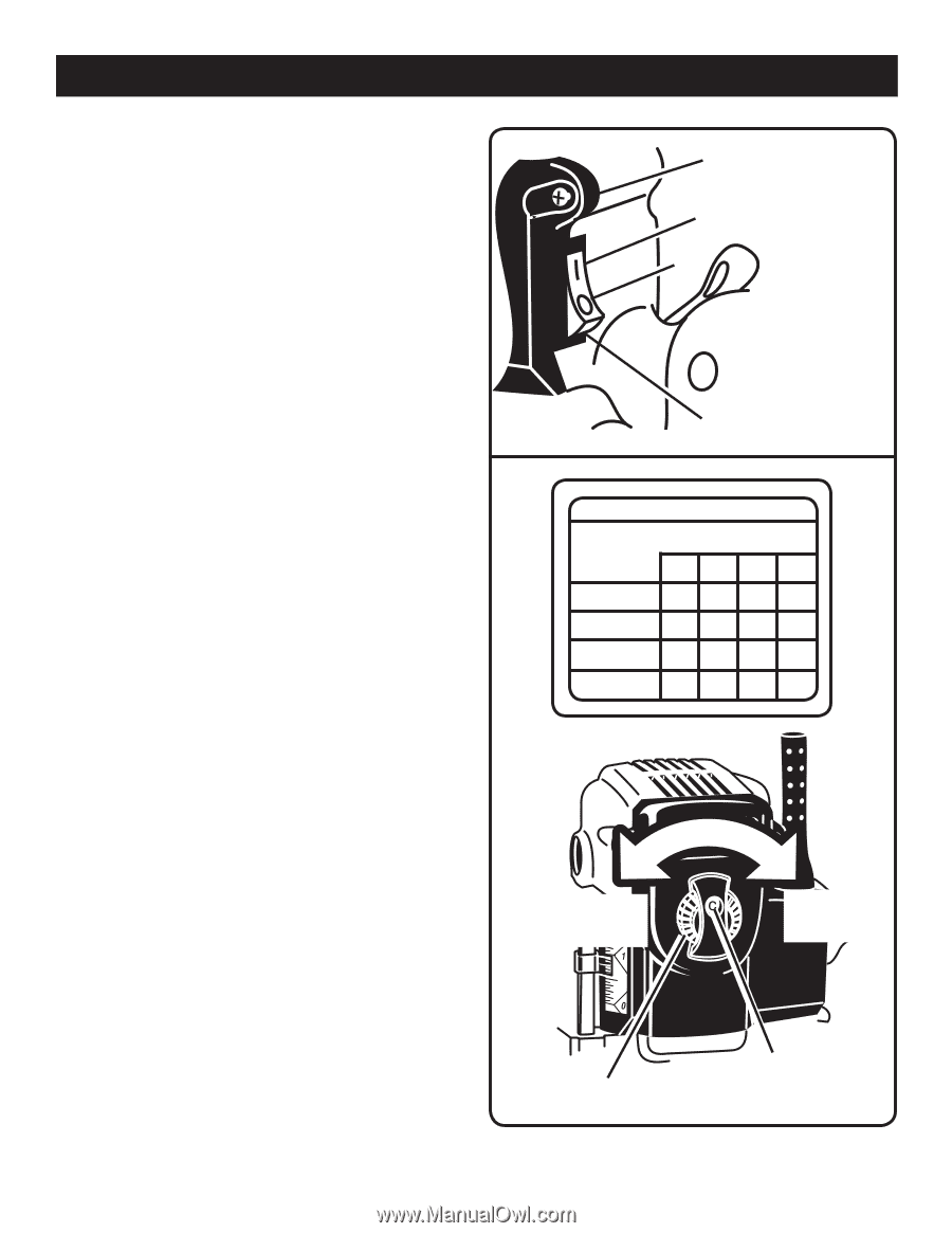
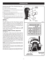
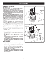
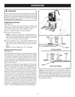
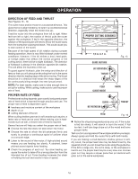
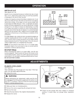
OPERATION To use the Accu-Stop™ Micro-Adjustable Depth Stop: Unplug the router. Loosen lock knob and raise stop bar. Rotate depth stop until the highest depth stop is aligned with the stop bar. Raise bit by unlocking plunge lock lever. Place router on flat surface, and lower router until tip of bit barely touches flat surface. Lock plunge lock lever to position bit at "zero" depth of cut. Lower stop bar against depth stop, then tighten lock knob securely. The highest stop now becomes the "zero" depth of cut setting. SWITCH See Figure 9. The router features a soft start which allows for a gradual increase in speed from 0 r/min. to the variable speed dial setting. For example, if the router is set at 15,000 r/min. at the time it is switched off and is then activated again, the motor is designed to gradually rev up to that speed instead of starting out at the full 15,000 r/min. To turn the router on, push the switch to the ( I ), or ON position. Return the switch to the ( O ), or OFF position when routing operation is finished. VARIABLE SPEED CONTROL SELECTOR See Figure 10. The router has a variable speed control selector designed to allow operator control of speed and torque limits. You can make speed selections best suited to the type of cut, the material being cut, and the size of bit being used. The variable speed control selector allows you to adjust router speed from 15,000 to 23,000 r/min. There is a six-step scale (A to F) on the variable speed control selector. To increase the speed and torque of the router, turn the variable speed control selector to a higher setting (F). Turn to a lower setting to decrease speed and torque. NOTE: If you do not want to use the variable speed control selector, turn it to the highest possible setting, and the feature will not be active. The speed selection chart shown gives suggested speed settings based on the diameter of the bit and the type of material being routed. We suggest that you practice with the variable speed feature of the router before installing a bit and making cuts in wood. MOTOR HOUSING ON OFF SWITCH Fig. 9 SPEED SELECTION CHART BIT SIZE MATERIAL 1/4 3/8 1/2 3/4 SOFT E-F D-E A-B A MEDIUM D-E C-D A A HARD C-D B-C A A VERY HARD D-E C-D C-D B-C TO INCREASE SPEED TO DECREASE SPEED VARIABLE SPEED CONTROL SELECTOR SPEED SELECTION SIGHT WINDOW Fig. 10 13
-
 1
1 -
2
-
3
-
4
-
5
-
6
-
7
-
 8
8 -
 9
9 -
 10
10 -
 11
11 -
 12
12 -
 13
13 -
 14
14 -
 15
15 -
 16
16 -
 17
17 -
 18
18 -
19
-
20
 |
 |