Ryobi RE180PL1G Operation Manual - Page 12
Zero Reset Indicator, Accu-stop™ Micro-adjustable, Depth Stop
 |
View all Ryobi RE180PL1G manuals
Add to My Manuals
Save this manual to your list of manuals |
Page 12 highlights
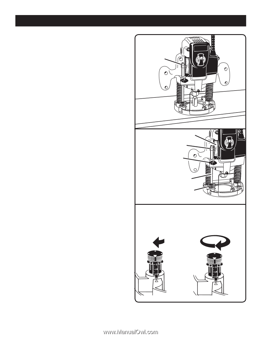
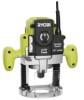
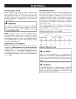
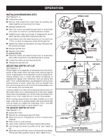
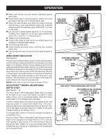
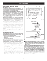
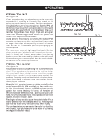
OPERATION Make sure the hex nuts are securely tightened against each other. Rotate depth stop to desired position, loosen lock knob and adjust stop bar until it touches depth stop. Slide zero reset indicator up or down the scale on stop bar until red line on zero reset indicator aligns with a desired reference point. For example, align red line with 1 in. mark on the scale. Lift stop bar to obtain desired depth of cut. For example, if setting 1/8 in. depth of cut, the zero reset indicator will move 1/8 in. from the 1 in. reference point. Tighten lock knob securely. Position the router so that the bit can extend below the subbase for desired depth setting. Unlock plunge lock lever. Grasp handles and lower router until stop bar contacts depth stop. Lock plunge lock lever to position bit at desired depth of cut. ZERO RESET INDICATOR See Figure 6. The zero reset indicator allows you to use the scale provided on the housing to make quick depth of cut changes to existing depth of cut settings. Simply choose a reference point on the scale and slide the zero reset indicator up or down the scale the distance required for new depth of cut. Then change stop bar position by loosening lock knob and adjusting stop bar until red line on zero reset indicator moves back to reference point. Tighten lock knob securely to lock stop bar in new position. The bit position will now increase or decrease the exact distance the stop bar was adjusted. NOTE: Each mark on the inch scale indicates 1/16 in. ACCU-STOP™ MICRO-ADJUSTABLE DEPTH STOP See Figures 7 - 8. The Accu-Stop™ Micro-Adjustable Depth Stop is located on the base of your router and makes it possible to make deep or heavy cuts in successive passes. Alignment marks make depth of cut changes quick and easy. A preset cutting depth is achieved by plunging router until stop bar comes in contact with depth stop. The microadjusting feature provides alignment marks at each 90° rotation of the depth stop knob. Each 90° rotation of the knob changes depth of cut setting 1/64 in. A complete 360° rotation of the knob changes the depth of cut setting 1/16 in. The Accu-Stop™ Micro-Adjustable Depth Stop provides for depth of cut changes to be made from 0 to 1/2 in. from the initial setting of the stop bar. This initial setting of the stop bar can be "zero" depth of cut, or it can be any depth of cut setting that you choose as a starting point for a particular job to be performed. ZERO RESET INDICATOR WITH RED LINE SCALE ZERO RESET INDICATOR WITH RED LINE LOCK KNOB Fig. 6 STOP BAR ACCU-STOPTM MICRO-ADJUSTABLE DEPTH STOP Fig. 7 ACCU-STOPTM MICRO-ADJUSTABLE DEPTH STOP EACH COMPLETE 360° ROTATION OF DEPTH STOP KNOB EQUALS 1/16 in. CHANGE IN DEPTH OF CUT EACH 90° ROTATION EQUALS 1/64 in. CHANGE IN DEPTH OF CUT Fig. 8 12
-
 1
1 -
2
-
3
-
4
-
5
-
6
-
 7
7 -
 8
8 -
 9
9 -
 10
10 -
 11
11 -
 12
12 -
 13
13 -
 14
14 -
 15
15 -
 16
16 -
 17
17 -
18
-
19
-
20
 |
 |