Ryobi RE180PL1G Operation Manual - Page 11
Installing/removing Bits, Selecting Depth Of Cut, To Adjust Depth Of Cut - plunge router
 |
View all Ryobi RE180PL1G manuals
Add to My Manuals
Save this manual to your list of manuals |
Page 11 highlights
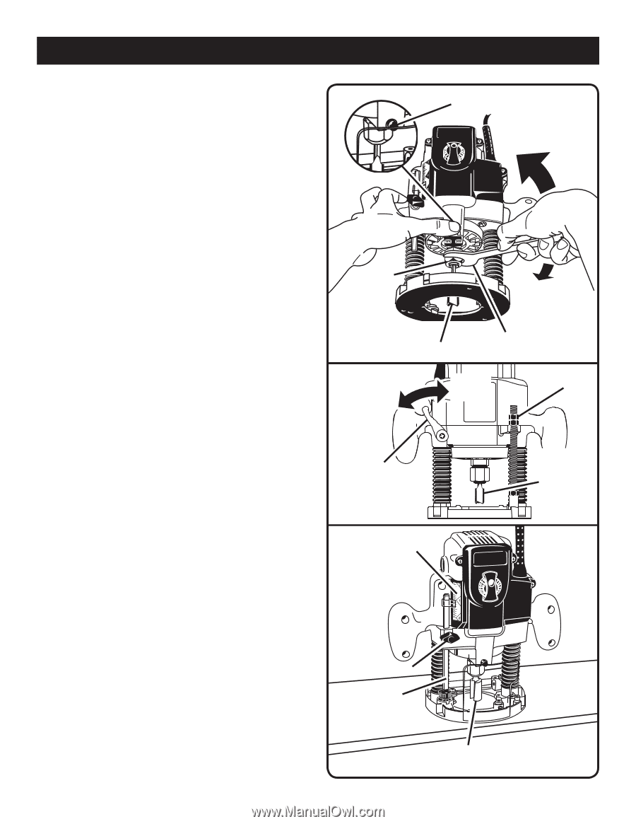
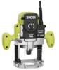
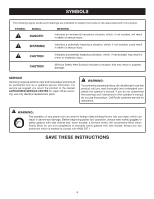
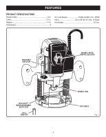
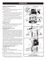
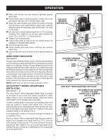
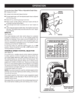
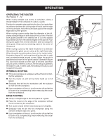
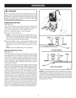
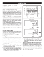
OPERATION INSTALLING/REMOVING BITS See Figures 2 - 3. Unplug the router. Remove chip shield from router base by pushing two sides together and removing from base. Depress spindle lock. Place the wrench provided through front of router base onto collet nut and turn counterclockwise to loosen. Install bit once collet nut is loose. If changing bits, bit will easily slip from collet after loosening collet nut. Insert shank of bit until shank bottoms out, then pull it out 1/16 in. to allow for expansion when the bit gets hot. Tighten the collet nut securely by turning clockwise with the wrench provided. Release spindle lock. Replace chip shield. To remove the bit: Place the wrench provided through front of router base onto collet nut and turn counterclockwise to loosen. Loosen the collet nut and remove the bit. Release the spindle lock. SELECTING DEPTH OF CUT See Figures 4 - 8. Proper depth of cut depends on several factors: the horsepower of the router motor, the type of bit, and the type of wood. A lightweight, low horsepower router is designed for making shallow cuts; a router with higher horsepower is designed for deeper cuts. Small bits, such as veining bits with 1/16 in. cutting diameters, are designed to remove only small amounts of wood. Large bits, such as straight-flute bits, remove larger amounts of wood and make deeper cuts in soft woods, such as white pine. Choose a depth of cut that will not place excessive strain on the router motor. If you need extra force or the motor speed slows down considerably, turn off the router and reduce the depth of cut. Then, make the cut in two or more passes. When routing a groove that is too deep to safely cut in one pass, make the cut in several passes. We recommend that cuts be made at a depth not exceeding 1/8 in. and that several passes be made to reach deeper cuts. TO ADJUST DEPTH OF CUT See Figures 4 - 8. Unplug the router. Raise bit by unlocking plunge lock lever. Adjust hex nuts on threaded post until bit is inside router subbase. Place router on a flat surface. Lower router until tip of bit barely touches flat surface. Lock plunge lock lever to position bit at "zero" depth of cut. Adjust hex nuts until they come in contact with stop flange. This will provide a position stop at "zero" depth of cut. 11 SPINDLE LOCK TO LOOSEN COLLET NUT COLLET NUT TO LOCK TO TIGHTEN COLLET NUT WRENCH BIT Fig. 3 TO UNLOCK HEX NUTS PLUNGE LOCK LEVER SCALE BIT INSIDE SUBBASE Fig. 4 LOCK KNOB STOP BAR TIP OF BIT TOUCHING WORKPIECE = ZERO DEPTH OF CUT Fig. 5
-
 1
1 -
2
-
3
-
4
-
5
-
 6
6 -
 7
7 -
 8
8 -
 9
9 -
 10
10 -
 11
11 -
 12
12 -
 13
13 -
 14
14 -
 15
15 -
 16
16 -
17
-
18
-
19
-
20
 |
 |