Ryobi RE180PL1G Operation Manual - Page 14
Internal Routing, Edge Routing, Operating The Router - edge guide
 |
View all Ryobi RE180PL1G manuals
Add to My Manuals
Save this manual to your list of manuals |
Page 14 highlights
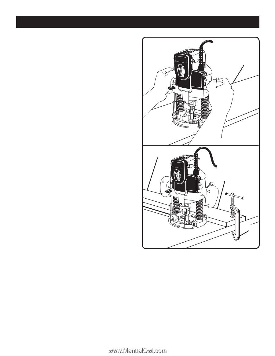
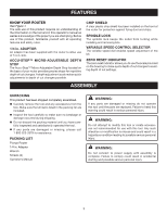
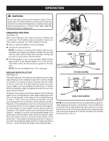
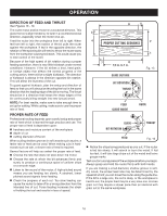
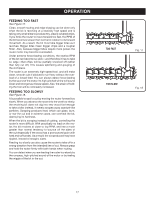
OPERATION OPERATING THE ROUTER See Figures 11 - 12. When routing straight cuts across a workpiece, clamp a straight edge to the workpiece to use as a guide. Position the straight edge parallel to the line of cut and offset the distance between the cutting edge of the bit and the edge of the router base. Hold the router base against the straight edge and rout the groove. When routing a groove wider than the diameter of the bit, clamp a straight edge on both sides of the cut lines. Position both guides parallel to the desired line of cut and spaced equal distances from the desired edges of the groove. Rout along one guide then reverse direction and rout along the other guide. Clean out any remaining waste in the center of the groove. When routing a groove, the travel should be in a direction that places the guide you are using at the right-hand side. When the guide is positioned as shown in the "guide inside" illustration (figure 16), tool travel should be from left to right and counterclockwise around curves. When the guide is positioned as shown in the "guide outside" illustration (figure 16), tool travel should be from right to left and clockwise around curves. If there is a choice, the first setup is generally the easier to use. In either case, the sideways thrust you use is against the guide. INTERNAL ROUTING Tilt router and place on workpiece without the bit contacting the workpiece. �Turn the router on and let the motor build up to full speed. �Gradually feed bit into the workpiece until the subbase is level with the workpiece. �Upon completion of the cut, turn the router off and let the bit come to a complete stop before removing the router from the workpiece. EDGE ROUTING �Clamp a straight edge to the workpiece as a guide. P�lace the router on the edge of the workpiece without the bit contacting the workpiece. Turn router on and let the motor build up to full speed. Gradually feed the bit into the workpiece �using the clamped straight edge as a guide. �Upon completion of the cut, turn the router off and let the bit come to a complete stop before removing the router from the workpiece. WORKPIECE 14 WORKPIECE Fig. 11 STRAIGHT EDGE CLAMP Fig. 12
-
 1
1 -
2
-
3
-
4
-
5
-
6
-
7
-
8
-
 9
9 -
 10
10 -
 11
11 -
 12
12 -
 13
13 -
 14
14 -
 15
15 -
 16
16 -
 17
17 -
 18
18 -
 19
19 -
20
 |
 |