Ryobi RTS12 Operation Manual - Page 16
To Assemble The Leg Stand, Mounting The Table Saw Base On The, Leg Stand
 |
View all Ryobi RTS12 manuals
Add to My Manuals
Save this manual to your list of manuals |
Page 16 highlights
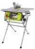
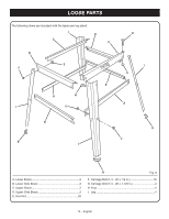
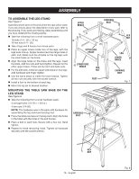
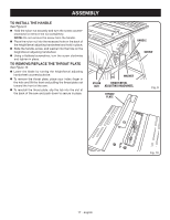
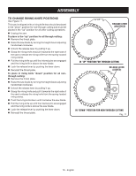
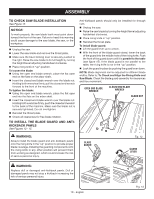
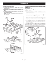
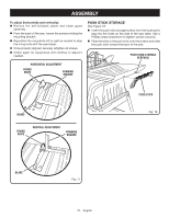
ASSEMBLY TO ASSEMBLE THE LEG STAND See Figure 7. Assembly is best done in the area where the saw will be used. If you are unsure about the description of any part, refer to the drawing. If any parts are missing, delay assembling until you have obtained the missing part(s). Take the following from a small hardware pack: 16 bolts (1/4 - 20 x 1/2 in.) 16 hex nuts (1/4 - 20) Take 4 legs and 8 braces from loose parts. Place an upper brace inside two of the legs, with the legs wide end up. (Upper braces have two large holes in each end.) Make sure the dimples on the leg align with the small holes on the brace. Align the large holes on the brace and the legs. Insert the bolts. Add hex nuts and hand tighten. Repeat for the other upper brace. These are the front and back sets. For the side sets, install an upper side brace on two legs. Add hardware and finger tighten. Use the same steps to install the lower braces. Tighten all hex nuts securely with the socket wrench. Install a foot to the bottom of each leg. Move the leg set to desired location. MOUNTING THE TABLE SAW BASE ON THE LEG STAND See Figure 8. Take the following from a small hardware pack: 4 carriage bolts (1/4-20 x 1-3/8 in.) 4 hex nuts (1/4-20) NOTE: This hardware was in the pack with hardware for assembling the leg stand and leveling feet. Place the table saw base on the leg stand. Align the holes in the table with the holes in the end braces. Place a bolt in each hole. Secure with a hex nut. Hand tighten. Repeat for three remaining holes. Tighten all hardware securely with the socket wrench. UPPER BRACE CARRIAGE BOLT HEX NUT UPPER SIDE BRACE LOWER SIDE BRACE HEX NUT FOOT LEG LOWER BRACE CARRIAGE BOLT Fig. 7 CARRIAGE BOLT HEX NUT 16 - English Fig. 8
-
 1
1 -
2
-
3
-
4
-
5
-
6
-
7
-
8
-
9
-
10
-
 11
11 -
 12
12 -
 13
13 -
 14
14 -
 15
15 -
 16
16 -
 17
17 -
 18
18 -
 19
19 -
 20
20 -
 21
21 -
22
-
23
-
24
-
25
-
26
-
27
-
28
-
29
-
30
-
31
-
32
-
33
-
34
-
35
-
36
-
37
-
38
-
39
-
40
-
41
-
42
-
43
-
44
-
45
-
46
-
47
-
48
-
49
-
50
-
51
-
52
-
53
-
54
-
55
-
56
-
57
-
58
-
59
-
60
-
61
-
62
-
63
-
64
-
65
-
66
-
67
-
68
-
69
-
70
-
71
-
72
-
73
-
74
-
75
-
76
-
77
-
78
-
79
-
80
-
81
-
82
-
83
-
84
-
85
-
86
-
87
-
88
-
89
-
90
-
91
-
92
-
93
-
94
-
95
-
96
-
97
-
98
-
99
-
100
-
101
-
102
-
103
-
104
-
105
-
106
-
107
-
108
-
109
-
110
-
111
-
112
-
113
-
114
-
115
-
116
 |
 |
