Ryobi RTS12 Operation Manual - Page 28
To Use The Miter Gauge, Heeling Paralleling The Blade To The, Miter Gauge Groove, Warning
 |
View all Ryobi RTS12 manuals
Add to My Manuals
Save this manual to your list of manuals |
Page 28 highlights
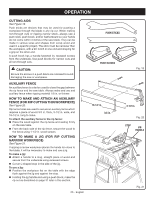
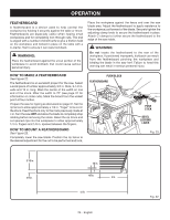
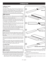
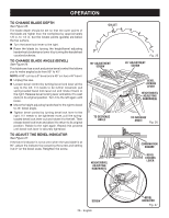
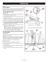
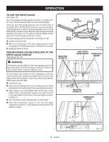
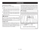
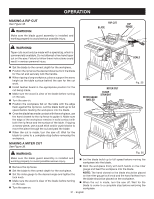
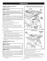
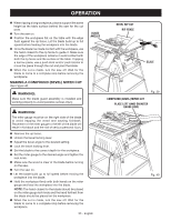
OPERATION TO USE THE MITER GAUGE See Figure 29. The miter gauge provides greater accuracy in angled cuts. For very close tolerances, test cuts are recommended. There are two miter gauge grooves, one on either side of the blade. When making a 90° cross cut, you can use either miter gauge groove. When making a beveled cross cut (the blade tilted in relation to the table) the miter gauge should be located in the groove on the right so that the blade is tilted away from the miter gauge and your hands. The miter gauge can be turned 60° to the right or left. Loosen the lock knob. With the miter gauge in the miter gauge groove, rotate the gauge until the desired angle is reached on the scale. Retighten the lock knob. HEELING (PARALLELING) THE BLADE TO THE MITER GAUGE GROOVE See Figures 30 - 32. WARNING: The blade must be parallel to the miter gauge groove so the wood does not bind resulting in kickback. Failure to do so could result in serious personal injury. Do not loosen any screws for this adjustment until you have checked with a square and made test cuts to be sure adjustments are necessary. Once the screws are loosened, these items must be reset. Unplug the saw. Remove the blade guard and anti-kickback pawls. Raise the blade by turning the height/bevel adjusting handwheel. Mark beside one of the blade teeth at the front of the blade. Place a combination square even with the front of the saw table and the side of the saw blade as shown in figure 31. Turn the blade so the marked tooth is at the back. Move the combination square to the rear and again measure the distance. If the distances are the same, the blade is square. MITER GAUGE BODY LOCK KNOB MITER GAUGE ADJUSTING SCREWS (2) Fig. 29 RIGHT MITER GAUGE GROOVE COMBINATION SQUARE ADJUSTING SCREWS (2) Fig. 30 COMBINATION SQUARE 28 - English Fig. 31
-
 1
1 -
2
-
3
-
4
-
5
-
6
-
7
-
8
-
9
-
10
-
11
-
12
-
13
-
14
-
15
-
16
-
17
-
18
-
19
-
20
-
21
-
22
-
 23
23 -
 24
24 -
 25
25 -
 26
26 -
 27
27 -
 28
28 -
 29
29 -
 30
30 -
 31
31 -
 32
32 -
 33
33 -
34
-
35
-
36
-
37
-
38
-
39
-
40
-
41
-
42
-
43
-
44
-
45
-
46
-
47
-
48
-
49
-
50
-
51
-
52
-
53
-
54
-
55
-
56
-
57
-
58
-
59
-
60
-
61
-
62
-
63
-
64
-
65
-
66
-
67
-
68
-
69
-
70
-
71
-
72
-
73
-
74
-
75
-
76
-
77
-
78
-
79
-
80
-
81
-
82
-
83
-
84
-
85
-
86
-
87
-
88
-
89
-
90
-
91
-
92
-
93
-
94
-
95
-
96
-
97
-
98
-
99
-
100
-
101
-
102
-
103
-
104
-
105
-
106
-
107
-
108
-
109
-
110
-
111
-
112
-
113
-
114
-
115
-
116
 |
 |
