Samsung RB195BSSB Service Manual
Samsung RB195BSSB Manual
 |
View all Samsung RB195BSSB manuals
Add to My Manuals
Save this manual to your list of manuals |
Samsung RB195BSSB manual content summary:
- Samsung RB195BSSB | Service Manual - Page 1
REFRIGERATOR RB195BSSW RB195BSSB RB195BSVQ RB195BSBB RB215BSSW RB215BSSB RB215BSVQ RB215BSBB REFRIGERATOR PRODUCT FEATURE q Reversible Door q Auto Ice-Maker q Fridge Wire Box SAM0070 - Samsung RB195BSSB | Service Manual - Page 2
The service guide is for service men with adequate backgrounds of electrical, electronic, and mechanical experience. Any attempt to repair a SAMSUNG ELECTRONICS AMERICA, INC. Technical Service Guide Copyright ⓒ2005 All rights reserved. This service guide may not be reproduced in whole or in part - Samsung RB195BSSB | Service Manual - Page 3
Contents 1. INSTALLATION 4 2. NOMENCLATURE 4 3. PRODUCT SPECIFICATIONS 5 4. ELECTRICAL PART SPECIFICATIONS & STANDARD 5 5. WARRANTY INFORMATION 7 6. INTERIOR VIEWS AND DIMENSIONS 8 7. REFRIGERATION CYCLE AND COOL AIR CIRCULATION ROUTE 10 8. MECHANICAL DISASSEMBLY 12 9. REVERSIBLE THE DOOR - Samsung RB195BSSB | Service Manual - Page 4
. 2. NOMENCLATURE 2005 Models R B 19 5 B S SB / XAA Company Name COLOR ; SB-STAINLESS PLATINUM, SW-SNOW WHITE VQ-BISQUE GLOSSY, BB-BLACK S : W2-PJT Buyer : BEST BUY OPTION ; BETTER Capacity ; 19:19CU,FT 21:21CU,FT B - BOTTOM MOUNTED FREEZER (BMF) Product ; R - REFRIGERATOR Label Location 4 - Samsung RB195BSSB | Service Manual - Page 5
3. PRODUCT SPECIFICATIONS Model Type Temperature control Net Capacity (ft3) Total Freezer Refrigerator Net dimension (W X D X H) Foam Cabinet insulation Door insulation Liner Cabinet Door Net weight(Ib) RB195BSSW, RB195BSSB, RB195BSVQ, RB195BSBB RB215BSSW, RB215BSSB, RB215BSBB, RB215BSVQ - Samsung RB195BSSB | Service Manual - Page 6
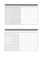
. 11Hrs 10±2min Freezer-Sensor Sensor Refrigerator-Sensor FRE Evap-Sensor THERMISTOR (502AT), SPEC:5.0KΩ AT 77℉ REF Evap-Sensor Ambient TEMP-Sensor Defrost Heater(FRE) 242W Heater Drain Heater(FRE) Defrost Heater(REF) 52W 120W Drain Heater(REF) 38W Ice-maker Heater 10W Fuse Thermal - Samsung RB195BSSB | Service Manual - Page 7
5. WARRANTY INFORMATION 7 - Samsung RB195BSSB | Service Manual - Page 8
Views and Dimensions 6-1) Shelves and Bins • Deli drawer Pull it out to disassemble. • Door Bin Push it up and slide it out to disassemble. Light • Glass Shelf Pull it out until its stop Tilt down and slide it out. • • • • • • • Gallon Bin • • Vegetable Drawer • Ice trays • Freezer Drawer - Samsung RB195BSSB | Service Manual - Page 9
Interior Views and Dimensions 6-2) Dimensions of Refrigerator (Inches) MODEL RB195 RB215 A B C 24.3 28.3 57.8 26.3 30.3 59.8 9 - Samsung RB195BSSB | Service Manual - Page 10
7. Refrigeration Cycle and Cool Air Circulation Route 7-1) Refrigerant Route in Refrigeration cycle Compressor → Sub condenser → Cluster pipe → Hot pipe → Dryer → Capillary tube → R-Evaporator → F-Evaporator → Accumulator → Suction pipe → Compressor 10 - Samsung RB195BSSB | Service Manual - Page 11
Refrigeration Cycle and Cool Air Circulation Route 7-2) Cool Air Circulation 11 - Samsung RB195BSSB | Service Manual - Page 12
8. Mechanical Disassembly Refrigerator Disassembly Control Panel 13 Refrigerator Light 14 Freezer Light 14 Evaporator Cover in the Refrigerator 15 Evaporator Cover in the Freezer 16 Evaporator in the Freezer 17 Evaporator in the Refrigerator 17 Machine Compartment & Electric Box 18 12 - Samsung RB195BSSB | Service Manual - Page 13
Mechanical Disassembly Control Panel 1. Remove the screws. 2. Pull out the control panel. 3. Disconnect the wire connector. 13 - Samsung RB195BSSB | Service Manual - Page 14
Mechanical Disassembly Always unplug the power cord before replacing the refrigerator lamp. There is the danger of electric shock. Warning Refrigerator Light 1. Remove the screw. Freezer Light 1. Remove the cover by pressing the bottom tab. 2. Remove the lamp cover by unlocking the tabs and - Samsung RB195BSSB | Service Manual - Page 15
Mechanical Disassembly Evaporator Cover in the Refrigerator 1. Remove all shelves and drawers from the refrigerator. 6. Disconnect the wire connector. 2. Pull out the screw caps with a small flat-blade screwdriver. 3. Remove 6 Phillps screws from the cover. ■Ductwork of the evaporator fan - Samsung RB195BSSB | Service Manual - Page 16
connector from the top-left corner. 2. Remove screws (2) from the support rail. 6. Remove 2 screws from the rear cover of the freezer evaporator and unlock the tabs to remove it. 2 screws 3. Pull down the holder of the support rail and disconnect the wire connector to remove it. ① ② 4. Unlock - Samsung RB195BSSB | Service Manual - Page 17
Evaporator is located in the bottom of refrigerator. 1. Take off the ductwork in refrigerator. 2. Disconnect the wire connector.(Heater and replacement dryer. 8. Evacuate and recharge the system using reasonable procedures. Evaporator in Freezer Evaporator is located in the bottom of freezer to - Samsung RB195BSSB | Service Manual - Page 18
before replacing any Warning electric components. 1. Unplug the power cord. 3. Mechine compartment assembly 4. Disassemble the electric box cover after removing the screws with a Phillips screwdriver. 2. Remove the screws of the compartment cover. Slide it up and take out from the refrigerator - Samsung RB195BSSB | Service Manual - Page 19
and carefully - IMPORTANT NOTES Unplug the refrigerator from its electrical outlet. Warning Empty all door guards / racks. 1. If you want to change the door direction, call 1-800-SAMSUNG. 2. Read the instructions carefully before starting. 3. Handle parts carefully to avoid scrathing paint. 4. Set - Samsung RB195BSSB | Service Manual - Page 20
REVERSING THE DOOR SWING Read these instructions completely and carefully 5. Disassemble the fridge door by lifting it upward. Be careful not to drop and scratch the fridge door. - ASSEMBLY OF FREEZER DOOR 8. After removing the screw, disassemble the Cover Hinge and the Hinge as below picture. - Samsung RB195BSSB | Service Manual - Page 21
REVERSING THE DOOR SWING Read these instructions completely and carefully 11. Assemble each part by exchanging its into the reverse side as below picture. 14. Assemble the each part into the reverse side as below picture. Assemble the Door S/W as it is. (Make sure not to insert it upside down) 12 - Samsung RB195BSSB | Service Manual - Page 22
REVERSING THE DOOR SWING Read these instructions completely and carefully 17. Assemble the assembled hinge and door to the refrigerator as below picture. Don't forget to insert washer with grease. 20. Assemble each part by exchanging its into the reverse side as below picture. Washer 18. Confirm - Samsung RB195BSSB | Service Manual - Page 23
Hinge 27. Finally, confirm openning and closing of the fridge door. 25. Assembling Hinge on the top of the refrigerator with the bolts. And then connect the electric wire. After door reversing, it is necessary to check and adjust the gasket whether it is entirely contact the cabinet or not. 23 - Samsung RB195BSSB | Service Manual - Page 24
. Follow these instructions carefully to minimize the risk of expensive water damage. • Banging pipes (water banging in the pipes) in house plumbing can cause damage to refrigerator parts and lead to water leakage or flooding. Call a qualified plumber to correct the problem before installing the - Samsung RB195BSSB | Service Manual - Page 25
and Super Cool Functions 27 11-4) Ice Off Function 29 11-5) Child Lock Function 29 11-6) Buzzer Alarm Function 30 11-7) Machine Compartment F-Fan Motor Delay Function 30 11-8) Ice Maker Function (Only applicable to Model with the Auto Ice Maker function) ∙∙∙31 11-9) Defrost Function 35 - Samsung RB195BSSB | Service Manual - Page 26
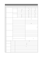
STD temperature for each step is as follows.(Based on 1/3H copper bar) Step Temp 1 2 3 4 5 6 7 8 9 10 11 12 8℉ 6℉ 4℉ 2℉ 0℉ -2℉ -4℉ -6℉ -8℉ -10℉ -12℉ -14℉ 1-5) When the Freezer button is pressed,7-SEG will be changed immediately.But, its function will go into operation in 10 seconds. 26 - Samsung RB195BSSB | Service Manual - Page 27
into operation in 10 seconds. 11-3) Super Freeze Function and Super Cool Functions 1) Super Freeze Function 1-1) It is selected by pressing the operation of Super Freeze,the fridge compartment will be controlled according to the Fridge Notch setting. D. The Freezer display will show the real - Samsung RB195BSSB | Service Manual - Page 28
half hours regardless of the Fridge compartment and with Super Cool, Comp and R-Fan will operate continuously until the Fridge compartment reaches to 28 ℉. Note When Super Freezer or Super Cool is selected with the Freezer temperature over 14 ℉ and the Fridge temperature over 50 ¢™F,it will operate - Samsung RB195BSSB | Service Manual - Page 29
Ice Off Function 1) Ice Off Function 1-1) Year 2005 W2 Model is one with Auto Ice Maker and Ice Water Valve. 1-2) When the Ice Off button is pressed,the Auto Ice Maker does not operate. 1-3) Ice stored in the ice bin is available with the Ice Off button selected. 1-4) The Auto Ice Maker will work. - - Samsung RB195BSSB | Service Manual - Page 30
Forced F/R-Defrost,it will send out a "BEEP"sound (0.5sec ON/0.5sec OFF). 11-7) Machine Compartment F-Fan Motor Delay Function 1) The refrigerator is to operating conditions with Comp on. So, make sure to take it into consideration during service. Machine Compartment Fan Delay Function Temp Range - Samsung RB195BSSB | Service Manual - Page 31
&Operation Functions 11-8) Ice Maker Function (Only applicable to Model with the Auto Ice Maker function) - This Ice Maker function is an option.So,the following can be applied only to Model mentioned. - Ice Maker has an automatic ice production function without extra controlling by users. It is - Samsung RB195BSSB | Service Manual - Page 32
Supply by comparing the temp changes of the Ice Maker Sensor on the bottom of the Ice Tray. If the temperature of the Ice Maker Sensor is 35.6 ℉(2 ℃) (5 COUNT) evaluated as No Water Supply. 2-4) Water Supply Operation Spec with Ice Test S/W Input - It will carry out water supply for once regardless of - Samsung RB195BSSB | Service Manual - Page 33
passed. At this time,the Ejection Standby time will be reset when it goes into F-Defrost during the standby and it will be recounted from the beginning after the completion of Defrost.Then, it checks if 58(58~110)minutes has passed.If the Ice Maker Sensor temp gets 5 ℉(-15℃)or lower and maintains it - Samsung RB195BSSB | Service Manual - Page 34
and carry out the normal ice making and ejection functions after checking the Ice Maker Sensor temperature in 90 minutes. Ice Tray is leveled horizontally.If not,it can be regarded as product failure.When the ice ejection stops upon the opening of the freezer door,the Test function does not work - Samsung RB195BSSB | Service Manual - Page 35
all the LEDs will be off. 1-2) When any of Super Freeze,Super Cool,Freezer and Fridge buttons is pressed within 15 seconds with the display panel shifted to the will not be changed (maintaining -14 ℉and 34℉) When Forced Defrost or Test Cancellation is selected within a minute after Forced Operation - Samsung RB195BSSB | Service Manual - Page 36
Function 2-1) When the Test button is pressed one more time during Forced Operation, it will go into R-Room Forced Defrost. Display for Forced R-Defrost -. Press one of Super Freeze, Super Cool, Freezer, Fridge buttons once during Forced Operation 2-2) When it is selected once more, it will go into - Samsung RB195BSSB | Service Manual - Page 37
Cool, Fridge or Freezer Cool and comes back on, it will carry out Super Cool when the FRoom temperature is lower than 41℉(5℃). But, the previously accumulated operating time will be reset defrost. - Press the Super Freeze and the Freezer repaired or when the Super Freeze button and the Super Cool - Samsung RB195BSSB | Service Manual - Page 38
Check List No Error LED Display 1 F-SENSOR ERROR Freezer Description F-SENSOR RELATED FAULT Others 2 R-SENSOR ERROR Fridge R-SENSOR RELATED FAULT 3 F-DEFROST SENSOR ERROR Freezer F-DEFROST SENSOR RELATED FAULT 4 R-DEFROST SENSOR ERROR Fridge R-DEFROST SENSOR RELATED FAULT 5 ICE MAKER - Samsung RB195BSSB | Service Manual - Page 39
0V. 122℉(+50℃)OR LOWER THAN 122℉(-50℃) SENSOR HOUSING SLIP-OUT, CONTACT 4 R-DEFROST SENSOR DEFECT, WIRE CUT, WIRE SHORT, SENSOR TEMP MORE THAN 122℉ VOLTAGE BETWEEN 3 TIMES OF ICE MAKER 9 FUNCTION KIT ICE EJECTION OR HORIZONTAL ERROR LEVELING ERROR ONLY APPLIED TO MODEL WITH ICE MAKER 39 - Samsung RB195BSSB | Service Manual - Page 40
- Self Diagnosis Check List LOAD DISPLAY OTHERS R-FAN R-Room second digit "a" Fridge R-DEFROST HEATER R-Room second digit "c" Fridge COMPRESSOR F-Room second digit "a" Freezer F-FAN F-Room second digit "b" Freezer F-DEFROST HEATER F-Room second digit "b" Freezer INITIAL START MODE - Samsung RB195BSSB | Service Manual - Page 41
will be shifted to the Option Setting Mode. How to Control Option Mode Shift Button by Model When the Super Cool and the Freezer buttons are pressed for 12 seconds at the same time, the Fridge/Freezer display will be shifted to the Option Setting Mode. Option Value Setting Down Key Option Value - Samsung RB195BSSB | Service Manual - Page 42
set values could be changed. Therefore, make sure to check quality information 2) After models whether they have Ice Maker or not. 5) With the same as the above method,R-Room Temp,Water Supply Qty, Ice Maker Eject Temp/Time,Defrost related to the refrigerator controlling.They are dropped here since - Samsung RB195BSSB | Service Manual - Page 43
Functions 11-16) Option Table 1) F-Room Temp Shift Table Set Item Model Option Item F-Room Temp Shift Common (All Models) LED:Fridge 0 Set Value F-Room Temp Set Value 0 1 2 3 4 .3℉(+3.5℃) 39.2℉(+4.0℃) Option Value Option Item Ex) When raising the fridge standard temperature by 28.4℉(-2℃) 43 - Samsung RB195BSSB | Service Manual - Page 44
Temp Control &Operation Functions 2) R-Room Temp Shift Table Set Item Model Option Item R-Room Temp Shift Common (All Models) LED:Fridge 1 Set Value F-Room Temp Set Value 0 1 2 3 4 5 6 7 8 9 10 11 12 13 14 15 Option Value 0 31.1℉(-0.5℃) 30.2℉(-1.0℃) 29.3℉(-1.5℃) 28.4℉(-2.0℃) 27.5℉(-2.5℃) 26 - Samsung RB195BSSB | Service Manual - Page 45
following options are only applicable to the models with Ice Maker. The following can not be set to the models without Ice Maker 3) Ice Maker Sensor Temp Shift This is the standard temperature checking if ice in the ice tray is frozen completely. 4) Ice Maker Water Supply Time Control Function It - Samsung RB195BSSB | Service Manual - Page 46
12. OPERATION PRINCIPLES BY PARTS OF CIRCUIT 12-1) SOURCE POWER CIRCUIT 47 12-2) OSCILLATION CIRCUIT 47 12-3) RESET CIRCUIT 48 12-4) EEPROM DETECTION CIRCUIT 48 12-5) DOOR SWITCH DETECTON CIRCUIT 48 12-6) TEMP SENSING CIRCUIT 49 12-7) ICE MAKER OPERATION CIRCUIT 50 12-8) DISPLAY DRIVING - Samsung RB195BSSB | Service Manual - Page 47
will supply DC5V to MICOM and power to other circuits via regulator REG2 (MC7805ACT),and make entire PCB operate. 12-2) OSCILLATION CIRCUIT Terminal Xin(#19) Xout(#18) Oscillation Freq for Resonator change,the timing system of MICOM changes resulting in errors. (Rated parts must be used) 47 - Samsung RB195BSSB | Service Manual - Page 48
allows the whole program to go back to the initial setting by initializing parts such as the RAM in MICOM with the power supply into MICOM or with an instant power failure. Upon the power supply,the reset terminal voltage becomes "LOW" for several tens of ㎲ compared to Vcc voltage(DC 5V - Samsung RB195BSSB | Service Manual - Page 49
temp coefficient of negative resistance and controls resistance.When the heat goes up,the resistance gets down and vice versa.R301~R305and C301~C303 are parts for noise prevention but they are not related to temp sensing characteristics. 2) If Vf is the incoming voltage to MICOM in case of F-Sensor - Samsung RB195BSSB | Service Manual - Page 50
PRINCIPLES BY PARTS OF CIRCUIT 12-7) ICE MAKER OPERATION CIRCUIT 1) The ice maker circuit above is to control the ice maker kit installed on the F room. This circuit is the hardware to control ejection and horizontal positioning,ice making temperature detection and full icing detection. Temperature - Samsung RB195BSSB | Service Manual - Page 51
OPERATION PRINCIPLES BY PARTS OF CIRCUIT 12-8) DISPLAY DRIVING CIRCUIT 1) KEY SCAN &DISPLAY DRIVING PRINCIPLE As shown in the wave diagram below,Micom sends out "high "signals through the - Samsung RB195BSSB | Service Manual - Page 52
for electronic refrigerators. 2) Compressor,F-Room,defrost heater,and other functions are controlled by relays. 3) For example,to operate the compressor,MICOM Pin #22 outputs high (5V)signals which go into IC70 Pin #7.The IC70 Pin #7 plays the same role as the base of NPN TR.The Pin #12 works as the - Samsung RB195BSSB | Service Manual - Page 53
OPERATION PRINCIPLES BY PARTS OF CIRCUIT 12-10) Buzzer Circuit Diagram 1) The circuit is buzzer. 4.7Kohm of R801 is a resistance for the production of quality buzzer sound. 12-11) MODEL OPTION CIRCUIT D601 ICE MAKER OPRION X • D602 USE NOT USE TEMP.OPTION X ℉ • ℃ D603 X • •* Diode( - Samsung RB195BSSB | Service Manual - Page 54
-5) When Defrost does not operate 63 13-6) When Alarm Sound continues without stop 65 13-7) Panel PCB Defect 66 13-8) When Room Lamp does not light up(F &R Rooms are the same 67 13-9) When Ice Water Valve does not operate (Option 69 13-10) When Ice Maker does not operate (Option:Model installed - Samsung RB195BSSB | Service Manual - Page 55
1.Check if power is supplied at Concent and Power Cord is connected properly before repair 2.Check by referring to the followings. Start Is Power of primery DC -TRANS ASS'Y NO Check assembly of NO wires and do repairing Change DC-TRANS NO Check PCB.REG1 NO (7812)/Change PCB Check PCB.REG2 ( - Samsung RB195BSSB | Service Manual - Page 56
Diagnostics 13-2) If there is a trouble with self-diagnosis 1) Ambient Sensor trouble =>(applied to Ambient Sensor Temp type) ERROR INDICATION Start Is Ambient Sensor normal?(At the top right hinge of the refrigerator) YES Is MAIN PCB (CN31) insertion normal? YES Is the connection wire between MAIN - Samsung RB195BSSB | Service Manual - Page 57
circuit explanation. YES Is MICOM Pin#51 input voltage normal? (Identical Voltage �~� of CN30) YES Change MAIN PCB 3) R-Room Defrost Sensor trouble Start Is R-Room Defrost Sensor normal? YES Is MAIN PCB (CN30) insertion normal? YES Is both trminal Voltage of MAIN PCB Connector CN30 �~� (PURPLE - Samsung RB195BSSB | Service Manual - Page 58
of the circuit explanation. Is MICOM Pin#51 input voltage normal? Identical Voltage �~� of CN30) YES Change MAIN PCB 5) F-Room Defrost Sensor trouble Start Is F-Room Defrost Sensor normal? YES Is MAIN PCB (CN30) insertion normal? YES Is both trminal Voltage of MAIN PCB �~� (ORANGE-BROWN - Samsung RB195BSSB | Service Manual - Page 59
pass 5 min after a desired Temp reached,COMP does not operate. 2. During Defrost,COMP does not operate. 3. With the disconnected F-Sensor or R-Sensor,COMP does Operation NO Soldering checkout/ Change MICOM or PCB NO Change or repair IC04/ NO Change PCB YES Check RELAY / Change PCB - Reference - Samsung RB195BSSB | Service Manual - Page 60
F-Room FAN, R-Room FAN and COMP COOLING FAN remains OFF while COMP is off. (R-FAN can be on with the defrost function.) 2. When Comp is ON,R-FAN S/W normal? YES Is the voltage of MICOM #42 5V (Close condition)? YES Freezer Door Switch input #42 Is insertion of CN71⑪PIN(YELLOW)of MAIN PCB normal? - Samsung RB195BSSB | Service Manual - Page 61
DOOR S/W normal? YES Is the voltage of MICOM #43 5V (Close condition)? Freezer Door Switch input #43 YES Is insertion of CN71(W/BLUE)of MAIN PCB normal? Start Forced Operation Normal R-FAN NO Check temp conditions, Select Super Cool NO Change DOOR S/W NO Check soldering /Change PCB NO Re- - Samsung RB195BSSB | Service Manual - Page 62
FAN does not operate Start NO Is COMP operating? YES Is it COMP COOLING FAN ON condition? YES Operate Forced Operation NO Stand by for FAN ON condition Confirm FAN operating condition Ambient Temp Range Load Operation Status Higher - Samsung RB195BSSB | Service Manual - Page 63
PANEL PCB KEY Press Super Cool and Fridge at the same time for 5 sec. Press any button 3 times when the entire display blinks. -.Once:Forced Operation -.Twice:R Defrost -.3 times:F/R Defrost -.4 times:Cancel A Dose Defrost start operating when F or R Forced Defrost button pushed? YES Is power - Samsung RB195BSSB | Service Manual - Page 64
return to the normal after Heating ? NO Is each concerned Defrost Sensor Temp higher than the terminated Temp? Refer to concerned Sensor resistance Temp? (Appendix.Temp Sensing Circuit Table) YES R Defrost Sensor #54 F Defrost Sensor #52 Change PCB YES Normal NO Standby until it reaches - Samsung RB195BSSB | Service Manual - Page 65
MICOM #43 & #42 "HIGH"(5V)? YES Normal R DOOR SIGNAL MICOM #43 OPEN :0V,CLOSE :5V F DOOR SIGNAL MICOM #42 OPEN :0V,CLOSE :5V NO Contact trouble of Connector CN30,Insert it again NO Repair DOOR S/W pressing part NO Change DOOR S/W NO Check DOOR S/W Circuit, Change PCB 65 - Samsung RB195BSSB | Service Manual - Page 66
Defrost. 2. It is checkable at Panel PCB when Forced Operation or Forced Defrost Is Forced Operation/Defrost selected? NO 't light up Start Cancel Forced Operation/Defrost PCB is normal Is PANEL PCB normal the change of the door opening direction. No Problem / Re-Check 66 NO Change PANEL PCB - Samsung RB195BSSB | Service Manual - Page 67
Diagnostics 2) When PANEL PCB Buttons do not work Start Is Connector of Upper Hinge Cover Room Lamp ON after opening Freezer Door. 2. Check F-Room Lamp OFF by pushing Door S/W. 3. Check R-Room with using the same method �,� after closing Freezer Door. 4. When it's problems, check Room Lamp and - Samsung RB195BSSB | Service Manual - Page 68
Diagnostics Start YES Is DOOR OPEN? YES Is DOOR SWITCH normal? YES Is Room LAMP(R,F) normal? Is the contact state of connector CN70 & CN71 normal? CN70 � PIN;F LAMP WIRE PIN CN71 � PIN;R LAMP WIRE PIN R DOOR SIGNAL MICOM #43 OPEN :0V,CLOSE :5V F DOOR SIGNAL MICOM #42 OPEN :0V,CLOSE :5V YES Are - Samsung RB195BSSB | Service Manual - Page 69
Make sure to avoid the electric shock while disassembling because one end of wire is applied with power. 3. Check the operation of the ice water valve only after the ice maker test switch is pressed. (F-Room Ice Maker) ICE PCB Normal - Check other parts ① Wire between ice water value and main PCB - Samsung RB195BSSB | Service Manual - Page 70
Ice Maker does not operate (Option:Model installed) Pre-Check 1. Water is automatically supplied to the Ice Maker and it dispenses cubed or crushed ice the Ice Maker Test S/W pressed? NO Is voltage applied to IC90 PIN #7 (DC11~12v)? YES Replace PCB YES Normal YES Check wires and Ice Maker Sensor - Samsung RB195BSSB | Service Manual - Page 71
or heat- deformed. � Repair or replace the defective power cord/outlet immediately. � Make sure the power cord is not punctuated or stomped down. ● Do not allow consumers to keep food unstable or place bottles in the Freezer Room. ● Do not allow consumers to repair the fridge for themselves. ● Do - Samsung RB195BSSB | Service Manual - Page 72
to MAIN PCB CN70,71 and measure followings LOAD MEASURING TERMINALS VALUE PCB MAIN DEFECTS OTHERS 1) F DEFROST HEATER 2) F DRAIN HEATER 1)R DEFROST HEATER 2)ICE WATER PIPE HEATER ICE WATER VALVE CN70 ⑬&⑦ CN71 ⑨&⑦ CN71 ①&⑤ 0 Ϊ THERMAL FUSE,HEATER,WIRE SHORT �Ϊ THERMAL FUSE,HEATER,WIRE CUT - Samsung RB195BSSB | Service Manual - Page 73
NO CONTACT SHORT,FAULTY DRIVING CIRCUIT K70 F DEFROST ON K72 CN70 ⑤-③ CN71 ⑬-⑨ 0V K70 CONTACT CN71 ③-CN70 ③ 0V SSR72 OPEN,FAULTY DRIVING CIRCUIT ICE WATER K74 CN71 ⑨-CN70 ③ 0V K74 NO CONTACT OPEN When there is problem,check the room lamps and the door switches. (Refer to 4-5.DOOR - Samsung RB195BSSB | Service Manual - Page 74
. 4. Measure resistance between CN30 ⑥ and ④ for F Defrost Sensor. 5. Measure resistance between CN31 ① and ④ for Ambient Sensor. 6. Compare the above values with current temps of Sensor locations (4-6.Temp Sensing Circuit Table)and Part Spec in Manual and evaluate them. 15-3) Others (Measure Load - Samsung RB195BSSB | Service Manual - Page 75
Regulator. 2. Oscillator generating clocks required for the MICOM program control &Reset circuit initializing programs upon power on/off. 3. EEPROM:It stores for model classifying options 8. It is the display driving part controlling the LEDs and the button signals. 9. It carries out the Ice Maker - Samsung RB195BSSB | Service Manual - Page 76
⑬F HEATER (F DRAIN) ①PANEL PCB WIRE ③PANEL GRID SIGNAL ⑤KEY ①,②ICE MAKER MOTOR ③GND ④ICE EJECT SENSOR ⑤TEST S/W ⑥HORIZONTAL S//W ⑦ICE FULL S//W ⑧GND ①F-DOOR S/W ②GND ③F-ROOM SENSOR ④F-DEFROST SENSOR ⑤R-DOOR S/W ⑥GND ⑦R-ROOM SENSOR ⑧R-DEFROST SENSOR ①AMBIENT SENSOR ④GND ①TRANS IN AC ③TRANS IN AC - Samsung RB195BSSB | Service Manual - Page 77
AC/DC POWER CIRCUIT OPTION CIRCUIT BUZZER CIRCUIT EEPROM RESET CIRCUIT OSCILLATOR CIRCUIT POWER CONTROL DRIVING PART CONTROL DOOR CONTROL AD CONVERT CONTROL TEST MODE CONTROL NORMAL MODE CONTROL STATUS CONTROL ICE MAKER CONTROL EEPROM CONTROL BUZZER CONTROL UART COMMUNICATION CONTROL DISPLAY - Samsung RB195BSSB | Service Manual - Page 78
19. CIRCUIT DIAGRAM 78 AC/DC POWER CIRCUIT DRIVING PART CONTROL CIRCUIT OSCILLATOR CIRCUIT RESET CIRCUIT BUZZER CIRCUIT SENSOR DETECTION CIRCUIT OPTION CIRCUIT DISPLAY CONTROL CIRCUIT ICE MAKER CONTROL CIRCUIT EEPROM CONTROL CIRCUIT - Samsung RB195BSSB | Service Manual - Page 79
20. WIRING SCHEMATIC 79 - Samsung RB195BSSB | Service Manual - Page 80
21. Temp to Resistance of Sensor &MICOM PORT Voltage Sensor CHIP:PX41C Standard ℃℉ V Ϊ℃℉ V Ϊ℃℉ V Ϊ -50 -58 4.694 153319 -5 23 3.107 16419 40 104 1.153 2997 -49 -56.2 4.677 144794 -4 24.8 3.057 15731 41 105.8 1.124 2899 -48 -54.4 4.659 136798 -3 26.6 3.006 15076 42 107.6 1.095 2805 -47 -52.6 4.641
-
 1
1 -
 2
2 -
 3
3 -
 4
4 -
 5
5 -
 6
6 -
 7
7 -
8
-
9
-
10
-
11
-
12
-
13
-
14
-
15
-
16
-
17
-
18
-
19
-
20
-
21
-
22
-
23
-
24
-
25
-
26
-
27
-
28
-
29
-
30
-
31
-
32
-
33
-
34
-
35
-
36
-
37
-
38
-
39
-
40
-
41
-
42
-
43
-
44
-
45
-
46
-
47
-
48
-
49
-
50
-
51
-
52
-
53
-
54
-
55
-
56
-
57
-
58
-
59
-
60
-
61
-
62
-
63
-
64
-
65
-
66
-
67
-
68
-
69
-
70
-
71
-
72
-
73
-
74
-
75
-
76
-
77
-
78
-
79
-
80
 |
 |
RB195BSSW
RB195BSSB
RB195BSVQ
RB195BSBB
RB215BSSW
RB215BSSB
RB215BSVQ
RB215BSBB
REFRIGERATOR
REFRIGERATOR
PRODUCT FEATURE
●
Reversible Door
●
Auto Ice-Maker
●
Fridge Wire Box