Samsung RB195BSSB Service Manual - Page 49
Temp Sensing Circuit
 |
View all Samsung RB195BSSB manuals
Add to My Manuals
Save this manual to your list of manuals |
Page 49 highlights
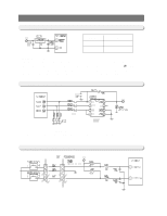
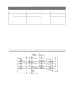
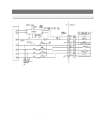
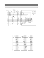
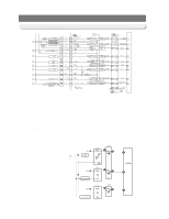
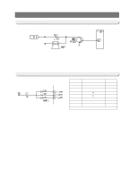
OPERATION PRINCIPLES BY PARTS OF CIRCUIT ITEM F DOOR OPEN/CLOSE CLOSE OPEN DOOR S/W CONTACT POINT OPEN CLOSE MICOM PIN NO # 42 MICOM INPUT "HIGH" "LOW" CLOSE R OPEN OPEN "HIGH" # 43 CLOSE "LOW" 1) If F-Door is opened,the contact point of the door switch (4-1)becomes closed.Then,the power of the PCB line flows to the door switch through R404 and 0V is applied to the MICOM terminal.And, when the door is closed,the contact point of the door switch (4-1)becomes open.Then,the power of the PCB line supplies 5V to MICOM via R404 and R401,which recognize the door as closed,turn on the fan at the extra load terminal and control the Room Lamp Relay (K73)turning off the lamp. 2) If R-Door is opened,the contact point of the door switch (2-1)becomes closed.Then,the power of the PCB line flows to the door switch through R403 and 0V is applied to the MICOM terminal.And, when the door is closed,the contact point of the door switch (2-1)becomes open.Then,the power of the PCB line supplies 5V to MICOM via R403 and R402,which recognize the door as closed,turn on the fan at the extra load terminal and control the Room Lamp Relay (K75)turning off the lamp. 12-6) TEMP SENSING CIRCUIT 1) Sensor uses a thermistor which has a temp coefficient of negative resistance and controls resistance.When the heat goes up,the resistance gets down and vice versa.R301~R305and C301~C303 are parts for noise prevention but they are not related to temp sensing characteristics. 2) If Vf is the incoming voltage to MICOM in case of F-Sensor,Vf equals (Rth *Vcc)/((R312 +Rth). Where Rth is resistance of THERMISTOR corresponding to Temp.Please refer to the Appendix Temp-to-Sensor Resistance/Voltage conversion table(Temp-to-MICOM Terminal Voltage included)on A/S. (Next page) 49
-
 1
1 -
2
-
3
-
4
-
5
-
6
-
7
-
8
-
9
-
10
-
11
-
12
-
13
-
14
-
15
-
16
-
17
-
18
-
19
-
20
-
21
-
22
-
23
-
24
-
25
-
26
-
27
-
28
-
29
-
30
-
31
-
32
-
33
-
34
-
35
-
36
-
37
-
38
-
39
-
40
-
41
-
42
-
43
-
 44
44 -
 45
45 -
 46
46 -
 47
47 -
 48
48 -
 49
49 -
 50
50 -
 51
51 -
 52
52 -
 53
53 -
 54
54 -
55
-
56
-
57
-
58
-
59
-
60
-
61
-
62
-
63
-
64
-
65
-
66
-
67
-
68
-
69
-
70
-
71
-
72
-
73
-
74
-
75
-
76
-
77
-
78
-
79
-
80
 |
 |
