Samsung RS257BABB Service Guide - Page 38
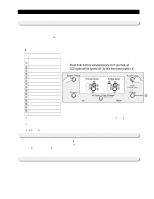
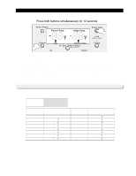
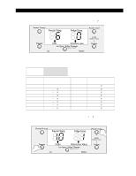
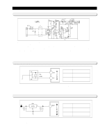
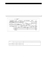
Source Power Circuit, 2 Oscillator Circuit, 3 Reset Circuit
 |
View all Samsung RS257BABB manuals
Add to My Manuals
Save this manual to your list of manuals |
Page 38 highlights
Circuit Descriptions 10-1) Source Power Circuit This circuit shows SMPS(Switch Mode Power Supply) which converts AC input voltage (115V, 60Hz) to a high DC voltage (170V). The input AC source power is converted to DC through a wave rectifier (BD1) and the converted DC power will generate a constant waveform on the switching transformer using a high speed (100KHz) switching motion of TOP223Y. The D104 will rectify the generated voltage and transform into a steady 12V DC source power used for the digital display panel and relays. The regulator (REG1) finally transforms into 5V DC source power for the control board and sensor's circuits. Caution) Be careful to handle this circuit due to high voltages (AC115V, DC170V) 10-2) Oscillator Circuit Terminal Oscillation Frequency 18 Xin(#19) 12MHz 19 Xout(#18) 12MHz This is oscillator circuit to generate synchronous clocks used to calculate the time for the microprocessor operation. Note) If the specification of a resonator changes, micro-processor can not work properly. 10-3) Reset Circuit 23 Terminal Voltage Vcc DC 5V RESET DC 0V The reset circuit is to initialize the values RAM & other sectors of micro-processor. When the power is engaged initially, the reset voltage becomes "Low," and it keeps "High" in the normal operation. 38
-
 1
1 -
2
-
3
-
4
-
5
-
6
-
7
-
8
-
9
-
10
-
11
-
12
-
13
-
14
-
15
-
16
-
17
-
18
-
19
-
20
-
21
-
22
-
23
-
24
-
25
-
26
-
27
-
28
-
29
-
30
-
31
-
32
-
 33
33 -
 34
34 -
 35
35 -
 36
36 -
 37
37 -
 38
38 -
 39
39 -
 40
40 -
 41
41 -
 42
42 -
 43
43 -
44
-
45
-
46
-
47
-
48
-
49
-
50
-
51
-
52
-
53
-
54
-
55
-
56
-
57
-
58
-
59
-
60
-
61
-
62
-
63
-
64
-
65
-
66
 |
 |
