Samsung RS257BABB Service Guide - Page 48
If there is a trouble with self-diagnosis
 |
View all Samsung RS257BABB manuals
Add to My Manuals
Save this manual to your list of manuals |
Page 48 highlights
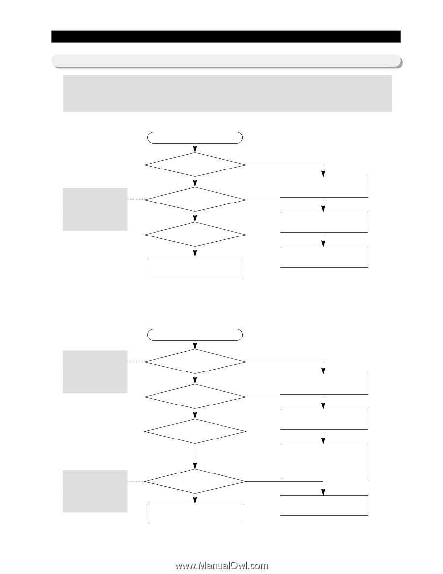
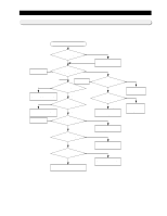
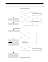
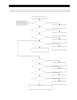
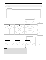
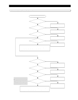
Diagnostics 11-4) If there is a trouble with self-diagnosis - Error of sensor can be seen on the front display of refrigerator. If power is impressed to refrigerator first, an failure of sensor is found. The refrigerator will stop working and display(blink) the region of trouble-occurred sensor repetitively. - Even if sensor has failure during the operation, the refrigerator will not stop working but can run the normal cooling operation because of being operated in the Emergency Operation mode. Therefore you' re requested to use how to check self-diagnosis(at page 26) in the manual. 1) If the ambient sensor has trouble Start � See Ref. 4 (descriptions of circuit operation, and how to check temperature sensor in the manual.) Was the Panel NO - PCB connector(CN10) inserted correctly? YES Is the ambient temperature NO sensor normal? YES Is the input of voltage to NO R301(Panel PCB) normal? A bad contact or connector missing? Exchange the temperature sensor. YES No trouble with PCB and temperature sensor. Recheck the contact failure of connector. Check the iced solder and short of main-PCB. 2) If the temperature sensor of R room has trouble - The sensor of freezer is connected in parallel with Bimetal. See the contents of Temperature Sensing Circuit section in the description of circuit operation. � See Ref.4 (descriptions of circuit operation, and how to check temperature sensor in the manual.) � For sensor resistance per temperature, make use of the resistance values from Ref. 4 and 5. Start Is the unit of NO Fridge's temperature sensor normal? YES Was the Main - PCB NO connector(CN30) inserted correctly? YES Is the sequence of NO insertion of connector(CN30) wire identical to the circuit diagram? YES Is the input voltage to NO MICOM pin No. 52 normal? YES No trouble with PCB and temperature sensor. Recheck the connector for an error of contact. Exchange the temperature sensor. Troubleshoot a bad contact or missing of connector. Modify the wrong configuration of connector wire -in case of being not inserted or incorrectly inserted - to be coincided with the circuit diagram. Check if the iced solder of main PCB is short. 48
-
 1
1 -
2
-
3
-
4
-
5
-
6
-
7
-
8
-
9
-
10
-
11
-
12
-
13
-
14
-
15
-
16
-
17
-
18
-
19
-
20
-
21
-
22
-
23
-
24
-
25
-
26
-
27
-
28
-
29
-
30
-
31
-
32
-
33
-
34
-
35
-
36
-
37
-
38
-
39
-
40
-
41
-
42
-
 43
43 -
 44
44 -
 45
45 -
 46
46 -
 47
47 -
 48
48 -
 49
49 -
 50
50 -
 51
51 -
 52
52 -
 53
53 -
54
-
55
-
56
-
57
-
58
-
59
-
60
-
61
-
62
-
63
-
64
-
65
-
66
 |
 |