Samsung RS257BABB Service Guide - Page 40
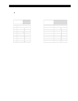
comes out from Q3, Q41, Q8, Q6, Q9, Q7, Q0, Q2, and Q4
 |
View all Samsung RS257BABB manuals
Add to My Manuals
Save this manual to your list of manuals |
Page 40 highlights
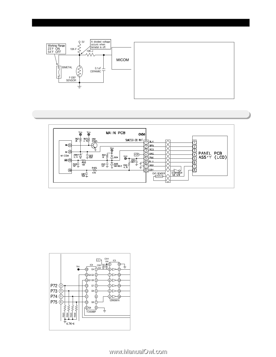
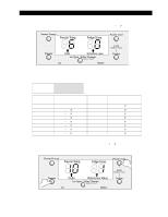
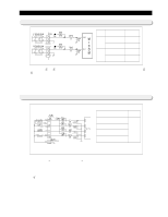
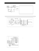
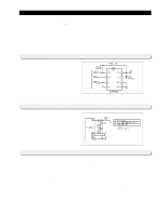
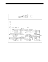
Circuit Descriptions 10-6) Display Circuit Note) 1) F-DEF-sensor and Bimetal work in parallel. 2) At the first power on, an open error (5V input to MICOM) can be detected by self-diagnostics. A short error will be ignored. 3) In self-diagnostics during a normal operation, only an open error can be detected. 4) The F-DEF heater will be off at the set temperature after the bimetal is off. The panel exchanges data through communication between Main PCB and Panel PCB. With the initial power on,Panel PCB gets information (temperature and settings)from Main PCB and displays it. At this time, it blinks at an interval of 0.5 sec On and 0.5 sec Off if there is communication problem between Main PCB and Panel PCB. The blinking continues until they communicate each other normally. And, when they communicate each other normally, it stops blinking immediately and displays normally. As shown in the figure, the panel picks up the Ambient Sensor and sends the information to Main PCB, and Main PCB directly picks up the Ice S/W. The Panel LCD Backlight lights up when there is an input signal such as Door Open or Button Input and the Backlight grows dim automatically, which is a power saving feature. 1) Key Scan and display operation. The model uses a decorder IC which 4 inputs and 9 outputs. If the IC 9 decorder (TC4028BP) receivesd signals from MICOM pins (3�6), an output signal per 2 miliseconds comes out from Q3, Q41, Q8, Q6, Q9, Q7, Q0, Q2, and Q4 pin in sequence. This signal enters to a driver IC input terminal of the CoolSelect ZoneTM PCB and IC5 (TD 62783AP), then approximate 11V peaks will generate from an output terminal as shown on the next page. 40
-
 1
1 -
2
-
3
-
4
-
5
-
6
-
7
-
8
-
9
-
10
-
11
-
12
-
13
-
14
-
15
-
16
-
17
-
18
-
19
-
20
-
21
-
22
-
23
-
24
-
25
-
26
-
27
-
28
-
29
-
30
-
31
-
32
-
33
-
34
-
 35
35 -
 36
36 -
 37
37 -
 38
38 -
 39
39 -
 40
40 -
 41
41 -
 42
42 -
 43
43 -
 44
44 -
 45
45 -
46
-
47
-
48
-
49
-
50
-
51
-
52
-
53
-
54
-
55
-
56
-
57
-
58
-
59
-
60
-
61
-
62
-
63
-
64
-
65
-
66
 |
 |