Samsung RS257BABB Service Guide - Page 57
Measuremenr Termina l
 |
View all Samsung RS257BABB manuals
Add to My Manuals
Save this manual to your list of manuals |
Page 57 highlights
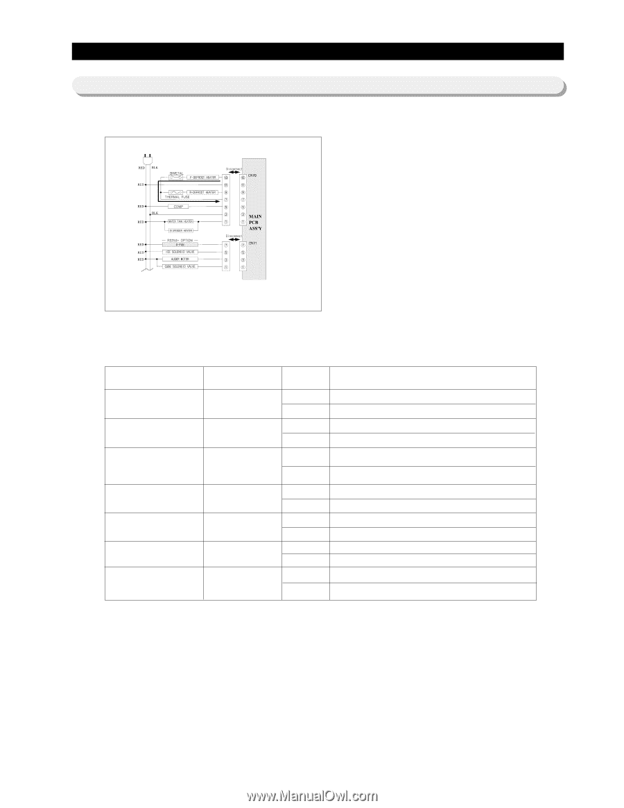
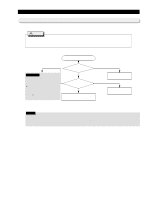
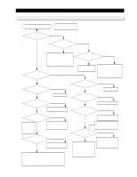
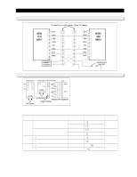
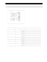
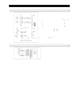
Reference for circuit diagnostics 12-3) Check a load Unplug the powercord and disconnect the main PCB CN70 and CN71, the measure the follows : 1. As shown in table below, measure the resistance between terminals, check load trouble and wire connection error. 2. The diagram of circuit was drawn based on the maximum load. When a repair is needed, see the electric wiring diagram on the back of refrigerator to troubleshoot the corresponding model. 3. For safety, you must turn the power off. Load Measuremenr Termina l Value Contents Freezer Def Heater between CN70 (13) 0Ϊ and CN70(7) ∞Ϊ Ref. Def Heater between CN70 (9) 0Ϊ and CN70(7) ∞Ϊ 1) Dispenser Heater between CN70 (11) 0Ϊ 2) Water Tank Heater and CN70(1) ∞Ϊ Ref. Fan Motor (RS253* Model) between CN70 (11) 0Ϊ and CN71(7) ∞Ϊ ICE SOLENOID VALVE AUGER MOTOR between CN70 (11) 0Ϊ and CN71(5) ∞Ϊ between CN70 (11) 0Ϊ and CN71(3) ∞Ϊ CUBE SOLENOID VALVE between CN70 (11) 0Ϊ and CN71(1) ∞Ϊ Temperature fuse, heater, wires short trouble Temperature fuse, heater, wires disconnection trouble Temperature fuse, heater, wires short trouble Temperature fuse, heater, wires disconnection trouble Heater, wires short trouble Heater, wires, and connector disconnection Coil, wires short trouble Coil, wires disconnection trouble Coil, wires short trouble Coil, wires disconnection trouble Coil, wires short trouble Coil, wires disconnection trouble Coil, wires short trouble Coil, wires disconnection trouble 57
-
 1
1 -
2
-
3
-
4
-
5
-
6
-
7
-
8
-
9
-
10
-
11
-
12
-
13
-
14
-
15
-
16
-
17
-
18
-
19
-
20
-
21
-
22
-
23
-
24
-
25
-
26
-
27
-
28
-
29
-
30
-
31
-
32
-
33
-
34
-
35
-
36
-
37
-
38
-
39
-
40
-
41
-
42
-
43
-
44
-
45
-
46
-
47
-
48
-
49
-
50
-
51
-
 52
52 -
 53
53 -
 54
54 -
 55
55 -
 56
56 -
 57
57 -
 58
58 -
 59
59 -
 60
60 -
 61
61 -
 62
62 -
63
-
64
-
65
-
66
 |
 |