Samsung SCC-641 Owners Instructions - Page 15
Setup Menu Overview
 |
UPC - 836164001306
View all Samsung SCC-641 manuals
Add to My Manuals
Save this manual to your list of manuals |
Page 15 highlights
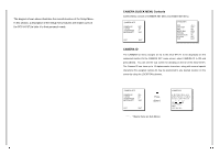
6. [Figure 6] Match the 3 holes on the back of the CAMERA and the CONNECTOR and turn it left about 15 degrees. (Check the sound of LOCKING and that the LEVER-LOCKING is in place) * Use the screws (BH M3XL8) to connect the CAMERA and the ADAPTER so they don't move. [Figure 6] 7. [Figure 7] Assemble the COVER-DOME onto the DOME. [Figure 7] Chapter 3 Setup Menu Overview In this chapter, we will look over the Setup Menu of the SCC-641(P), First we'll look over the overall structure of the Setup Menu, and then we'll look at the functions of each menu.
-
 1
1 -
2
-
3
-
4
-
5
-
6
-
7
-
8
-
9
-
 10
10 -
 11
11 -
 12
12 -
 13
13 -
 14
14 -
 15
15 -
 16
16 -
 17
17 -
 18
18 -
 19
19 -
 20
20 -
21
-
22
-
23
-
24
-
25
-
26
-
27
-
28
 |
 |
Chapter 3
Setup Menu Overview
In this chapter, we will look over the Setup Menu of the SCC-641(P),
First we'll look over the overall structure of the Setup Menu, and then
we'll look at the functions of each menu.
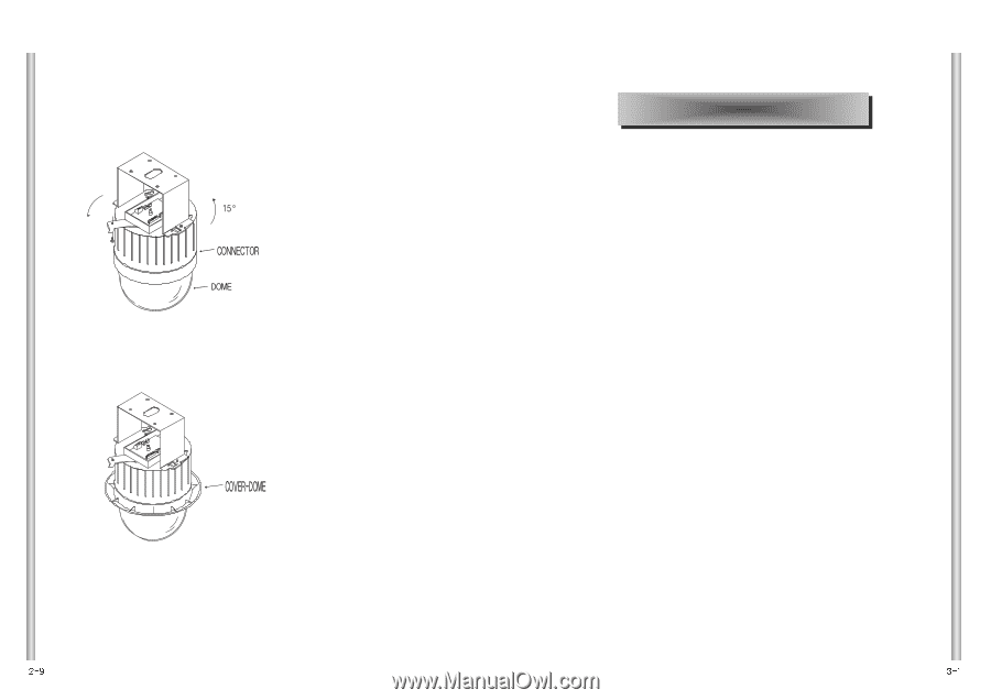
6. [Figure 6] Match the 3 holes on the back of the CAMERA and the CONNECTOR
and turn it left about 15 degrees.
(Check the sound of LOCKING and that the LEVER-LOCKING is in place)
* Use the screws (BH M3XL8) to connect the CAMERA and the ADAPTER
so they don't move.
[Figure 6]
7. [Figure 7] Assemble the COVER-DOME onto the DOME.
[Figure 7]