Samsung SMT-190DN User Manual - Page 6
Unpacking, Names and Functions of Parts - user manual
 |
UPC - 036725120174
View all Samsung SMT-190DN manuals
Add to My Manuals
Save this manual to your list of manuals |
Page 6 highlights
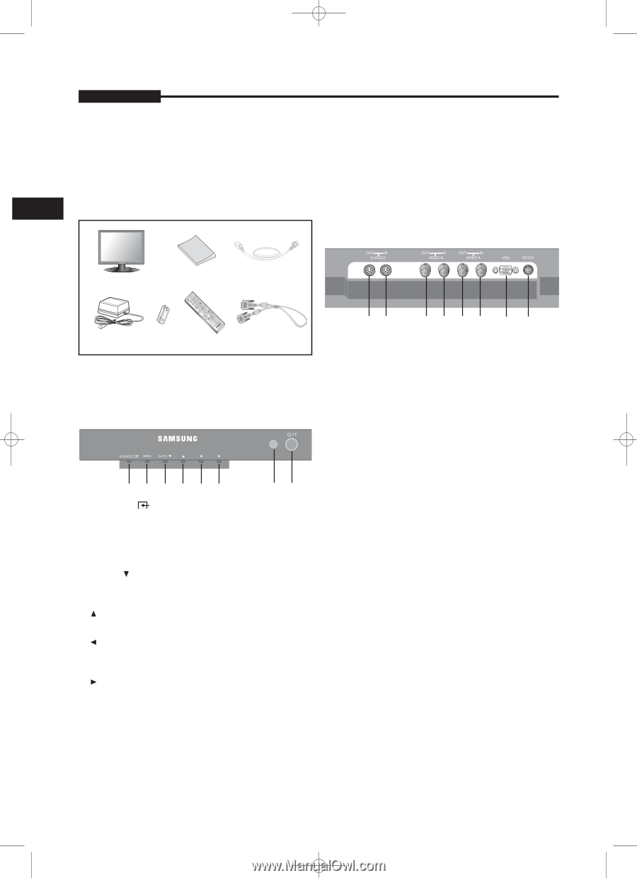
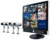
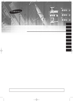
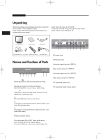
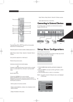
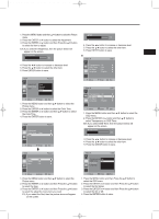
SMT-171/SMT-190-ENG 12/8/05 9:40 AM Page 6 USER'S MANUAL Unpacking Remove the package cover and place the product on a flat and green when the power is turned ON. secure surface or in the installation location. The power is turned off by pressing the power switch Check whether all the following devices and accessories are again and the power LED goes off. E included with the main system. Bottom Panel Control TFT-LCD MONITOR USER'S MANUAL POWER CORD AC POWER ADAPTOR BATTERIES REMOTE CONTROLLER VGA SIGNAL CABLE Names and Functions of Parts Front Key Control 123456 78 1. SOURCE / Select input source, and move the previous menu. 2. MENU Activates and exits the On Screen Display. OSD MENU(MAIN) : Input, Picture, OSD, Setup. 3. AUTO / ‚ (DOWN) This button is move the OSD menu, and use to auto adjustment of VGA input only. 4. › (UP) Move the OSD main menu or sub menu. 5. ¥ (LEFT) This button is decrease the level of active function, and move the previous menu. 6. Š (RIGHT) This button is increase the level of active function, and select OSD menu. 7. IR Sensor Remote controller sensor. 8. POWER ON/OFF Turns the power ON or OFF. There will be a few seconds delay before the display appears. The power LED(next to the power switch) lights with 87 6543 1. DC 12V IN DC power Input. 2. VGA IN VGA Signal Input. 3. VIDEO A IN Composite signal Input for VIDEO A 4. VIDEO A OUT Video looping output for VIDEO A 5. VIDEO B IN Composite signal Input for VIDEO B 6. VIDEO B OUT Video looping output for VIDEO B 7. S-VIDEO (Y/C) IN Y/C separated signal input 8. S-VIDEO (Y/C) OUT Y/C separated signal looping output 2 1 -6-
-
 1
1 -
 2
2 -
 3
3 -
 4
4 -
 5
5 -
 6
6 -
 7
7 -
 8
8 -
 9
9 -
 10
10 -
 11
11 -
 12
12 -
13
-
14
-
15
-
16
-
17
-
18
-
19
-
20
-
21
-
22
-
23
-
24
-
25
 |
 |