Sanyo HECSR1000K Service Manual - Page 14
Remote control, Back cover, Up/Down pulse PWB ass'y, BOAD ASS'Y UP/DOW PULSE and remove
 |
UPC - 864830542112
View all Sanyo HECSR1000K manuals
Add to My Manuals
Save this manual to your list of manuals |
Page 14 highlights
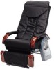
Replacement Procedure HEC-DR21 (TAIWAN) (5) Replacement of remote control section 1, Disconnect connector CN11 connected to PRINTED BOAD ASS'Y (MAIN). 2, Detach bushing of remote control cord and remove remote control section. 3, Unscrew five remote control case set screws and open remote control case vertically. Photo.5 (6) How to detach COVER (BACK COVER) 1, Unscrew four COVER (BACK COVER) set screws and remove COVER (BACK COVER). Photo.7 COVER (BACK COVER) COUTION LAVEL(REMOTE CONTROL) SCREW SCREW Photo.5 Photo.7 4, Unscrew one PRINTED BOAD ASS'Y (REMOTE CONTORL) (7) Replacement of PRINTED BOAD ASS'Y (UP/DOW PULSE) set screw and disconnect connector of CONNECTOR 1, Unscrew two cover set screws and remove cover. ASS'Y. Photo.6 2, Pull out four connectors connected to PRINTED 5, Unscrew all the sensor set screws and remove BOAD ASS'Y (UP/DOW PULSE) and remove PRINTED BOAD ASS'Y (SENSOR A)(SENSOR B). PRINTED BOAD. Photo.8 Photo.6 3, Unscrew one CONDENSER ASS'Y set screw SCREW PRINTED BOAD ASS'Y (SENSOR A) and remove CONDENSER ASS'Y. Photo.8 CONDENSER ASS'Y SCREW PRINTED BOAD ASS'Y (SENSOR A) PRINTED BOAD ASS'Y(REMOTE CONTPRL) CONNECTOR ASS'Y Photo.6 PRINTED BOAD ASS'Y (UP/DOW PULSE) COVER Photo.8 - 14 -
-
 1
1 -
2
-
3
-
4
-
5
-
6
-
7
-
8
-
 9
9 -
 10
10 -
 11
11 -
 12
12 -
 13
13 -
 14
14 -
 15
15 -
 16
16 -
 17
17 -
 18
18 -
 19
19 -
20
 |
 |
