Schwinn 430 Elliptical Assembly Manual - Page 10
Step 1 Install Rear Stabilizer and Extrusion Handlebar - assembly instructions
 |
View all Schwinn 430 Elliptical manuals
Add to My Manuals
Save this manual to your list of manuals |
Page 10 highlights
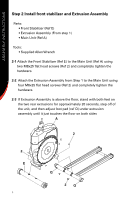
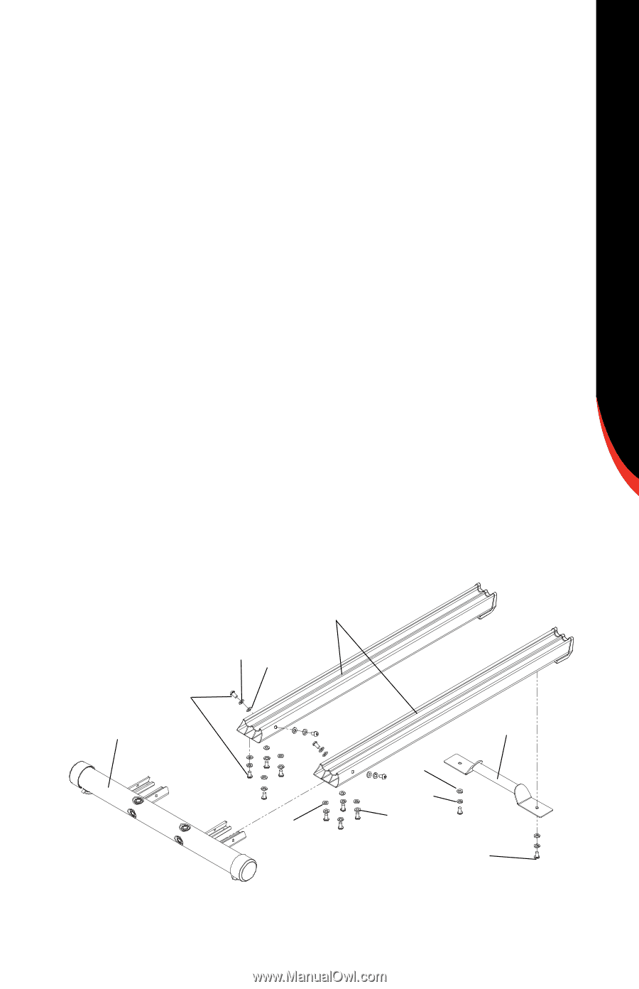
ASSEMBLY INSTRUCTIONS Step 1 Install Rear Stabilizer and Extrusion Handlebar Parts: • Two Extrusion Assemblies (Ref. H) • Rear Stabilizer (Ref. G ) • Extrusion Handlebar Assembly (Ref. I) Tools Supplied Allen Wrench 1-1 Attach, but do not tighten, the Extrusion Assemblies (Ref H) to the Rear Stabilizer Assembly (Ref G) using twelve M8x15L button head (Ref 1) twelve M8 washers locking (Ref 5) and twelve M8 washers regular (Ref 3). 1-2 Attach the Extrusion Handlebar Assembly (Ref I) to the Extrusion Assemblies using two M8x15L button head (Ref 1), two M8 washers locking (Ref 5) and two M8 washers regular (Ref 3). 1-3 Completely tighten all of the Hardware. H 53 1 G I 3 5 3 5 1 7
-
 1
1 -
2
-
3
-
4
-
 5
5 -
 6
6 -
 7
7 -
 8
8 -
 9
9 -
 10
10 -
 11
11 -
 12
12 -
 13
13 -
 14
14 -
 15
15 -
16
-
17
-
18
-
19
-
20
-
21
 |
 |
7
ASSEMBLY INSTRUCTIONS
Step 1 Install Rear Stabilizer and Extrusion Handlebar
Parts:
•
Two Extrusion Assemblies (Ref. H)
•
Rear Stabilizer (Ref. G )
• Extrusion Handlebar Assembly (Ref. I)
Tools:
• Supplied Allen Wrench
1-1
Attach, but do not tighten, the Extrusion Assemblies (Ref H)
to the Rear Stabilizer Assembly (Ref G) using twelve
M8x15L button head (Ref 1) twelve M8 washers locking
(Ref 5) and twelve M8 washers regular (Ref 3).
1-2
Attach the Extrusion Handlebar Assembly (Ref I) to the Extrusion
Assemblies using two M8x15L button head (Ref 1),
two M8 washers locking (Ref 5) and two M8 washers regular
(Ref 3).
1-3
Completely tighten all of the Hardware.
H
G
I
1
3
3
3
1
5
5
5