Schwinn 430 Elliptical Assembly Manual - Page 17
Step 8 Install Right and Left Foot Assembly
 |
View all Schwinn 430 Elliptical manuals
Add to My Manuals
Save this manual to your list of manuals |
Page 17 highlights
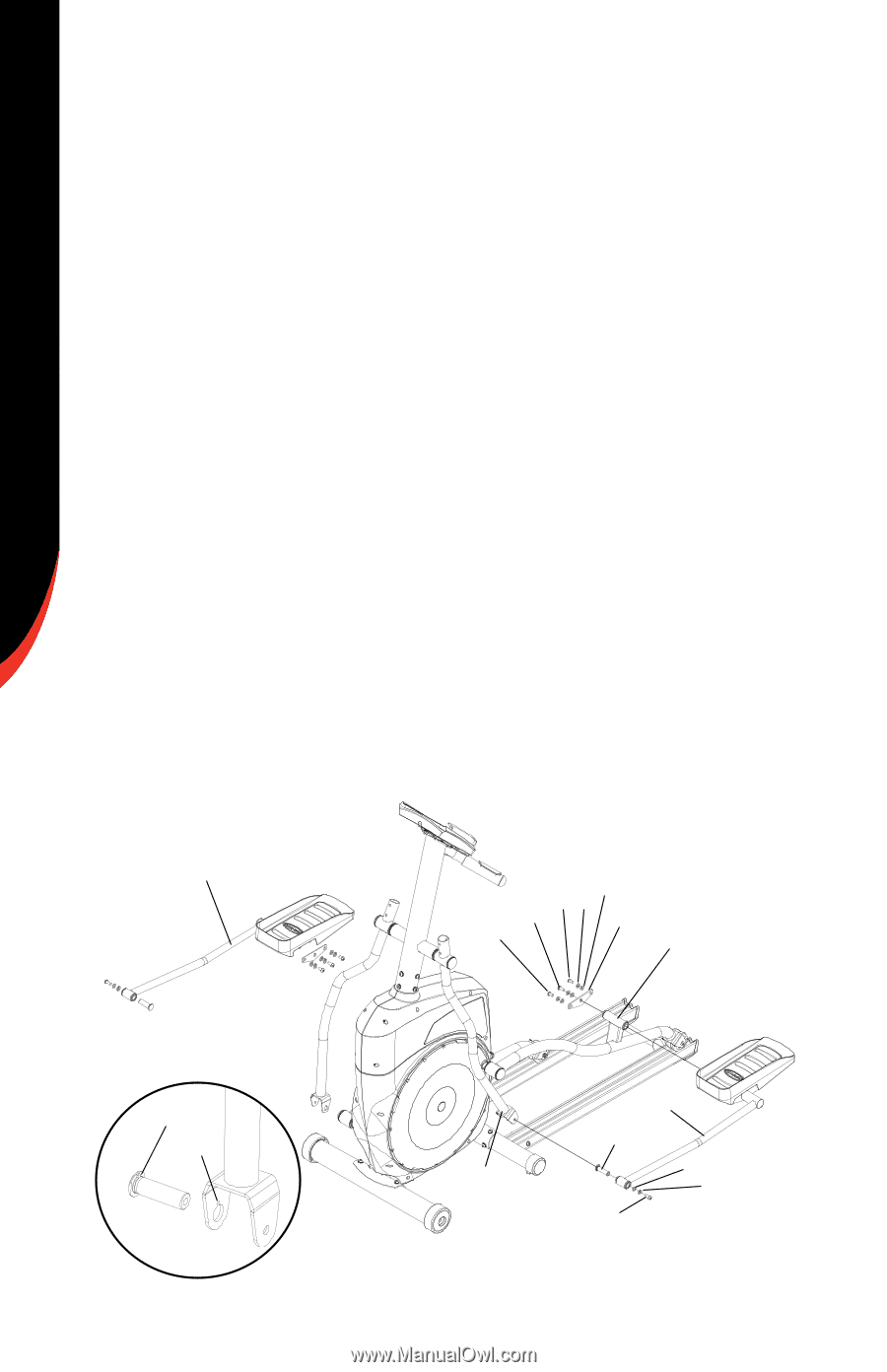
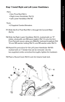
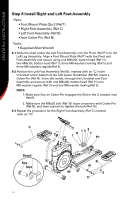
ASSEMBLY INSTRUCTIONS Step 8 Install Right and Left Foot Assembly Parts Foot Mount Plate Qty.2 (Ref T Right Foot Assembly (Ref C Left Foot Assembly (Ref B Arm Cotter Pin (Ref N) Tools Supplied Allen Wrench 8-1 Slide the shaft under the Left Foot Assembly into the Pivot (Ref P1) on the Left Leg Assembly. Align a Foot Mount Plate (RefT) with the Pivot and Foot assembly and secure using one M8x20L button head (Ref 11), two M8x15L button head (Ref 1), three M8 washers locking (Ref 5) and three M8 washers regular(Ref 3). 8-2 Position the Left Foot Assembly (Ref B), marked with an "L", in the U bracket at the bottom of the Left Lower Handlebar (Ref M). Insert a Cotter Pin (Ref N) , from the inside, through the U bracket and Foot Assembly and secure with one M8x20L button head (Ref 11) one M8 washer regular (Ref 3) and one M8 washer locking(Ref 5). NOTE: 1. Make sure Key on Cotter Pin engages the Slot in the U bracket. (see detail). 2. Make sure the M8x20 bolt (Ref 10) stays concentric with Cotter Pin (Ref N), and then use tool to tighten the bolt (Ref 10). 8-3 Repeat the procedure for the Right Foot Assembly (Ref C) marked with an "R". C 153 1 11 T P1 Detail Key Slot 14 B N M 3 5 11
-
 1
1 -
2
-
3
-
4
-
5
-
6
-
7
-
8
-
9
-
10
-
11
-
 12
12 -
 13
13 -
 14
14 -
 15
15 -
 16
16 -
 17
17 -
 18
18 -
 19
19 -
 20
20 -
 21
21
 |
 |