Seagate 600 SSD Seagate 600 SSD Product Manual - Page 21
Drive Mounting - 5mm
 |
View all Seagate 600 SSD manuals
Add to My Manuals
Save this manual to your list of manuals |
Page 21 highlights
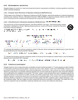
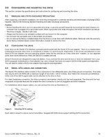
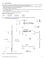
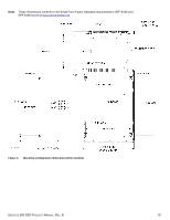
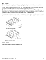
3.4 DRIVE MOUNTING You can mount the drive in any orientation using four screws in the side-mounting holes or four screws in the bottommounting holes. Follow these important mounting precautions when mounting the drive: • Allow a minimum clearance of 0.030 in (0.76 mm) around the entire perimeter of the drive for cooling as a guideline. Please refer to Section 3.5 for final cooling requirements. • Use only M3 x 0.5 metric mounting screws. • Four (4) threads (0.080 in) minimum screw engagement recommended. Also ensure maximum screw length does not bot- tom out in mounting holes. • Do not overtighten the mounting screws (maximum torque: 4.5 in-lb, ± 0.45 in-lb). Refer to 4 for detailed mounting configuration dimensions. See Section 3.4, "Drive mounting." Weight: 7mm models 5mm models 0.170 pounds 0.148 pounds 77 grams 67 grams Note. These dimensions conform to the Small Form Factor Standard documented in SFF-8201 and SFF-8223 found at www.sffcommittee.org. Figure 3. Mounting configuration dimensions (7mm models) SEAGATE 600 SSD PRODUCT MANUAL, REV. B 17
-
 1
1 -
2
-
3
-
4
-
5
-
6
-
7
-
8
-
9
-
10
-
11
-
12
-
13
-
14
-
15
-
 16
16 -
 17
17 -
 18
18 -
 19
19 -
 20
20 -
 21
21 -
 22
22 -
 23
23 -
 24
24 -
 25
25 -
 26
26 -
27
-
28
-
29
-
30
-
31
-
32
-
33
-
34
-
35
-
36
-
37
-
38
-
39
 |
 |
