Seagate 600 SSD Seagate 600 SSD Product Manual - Page 25
Table 7, 8 SATA Connector Plug Pinout
 |
View all Seagate 600 SSD manuals
Add to My Manuals
Save this manual to your list of manuals |
Page 25 highlights
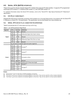
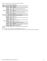
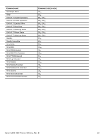
Table 7 summarizes the 1.8" drive Signal and Power SATA Plug. Table 7 1.8" SATA Connector Plug Pinout Segment Signal Power Pin Function Definition S1 GND Ground S2 A+ Differential Signal Pair (Host to Drive) S3 A- S4 GND Ground S5 B- Differential Signal Pair (Drive to Host) S6 B+ S7 GND Ground Spacing separates signal and power segments P1 V33 Unused [2] P2 V33 P3 GND Ground [1] P4 GND P5 V5 5V power to Drive P6 V5 P7 LED Signal Activity LED: Driven low to light Key Key Keyway P8 Optional Reserved for Seagate use. P9 Optional Leave unconnected. Notes: [1] Ground pins 3 and 4 mate first on micro SATA backplane connectors [2] The two V33 pins are unused but connected together on the drive. They can be used for a drive-in-place detection. SEAGATE 600 SSD PRODUCT MANUAL, REV. B 21
-
 1
1 -
2
-
3
-
4
-
5
-
6
-
7
-
8
-
9
-
10
-
11
-
12
-
13
-
14
-
15
-
16
-
17
-
18
-
19
-
 20
20 -
 21
21 -
 22
22 -
 23
23 -
 24
24 -
 25
25 -
 26
26 -
 27
27 -
 28
28 -
 29
29 -
 30
30 -
31
-
32
-
33
-
34
-
35
-
36
-
37
-
38
-
39
 |
 |
