Seagate ST3300457FC Cheetah 15K.5 SCSI Product Manual - Page 28
Physical/electrical specifications
 |
View all Seagate ST3300457FC manuals
Add to My Manuals
Save this manual to your list of manuals |
Page 28 highlights
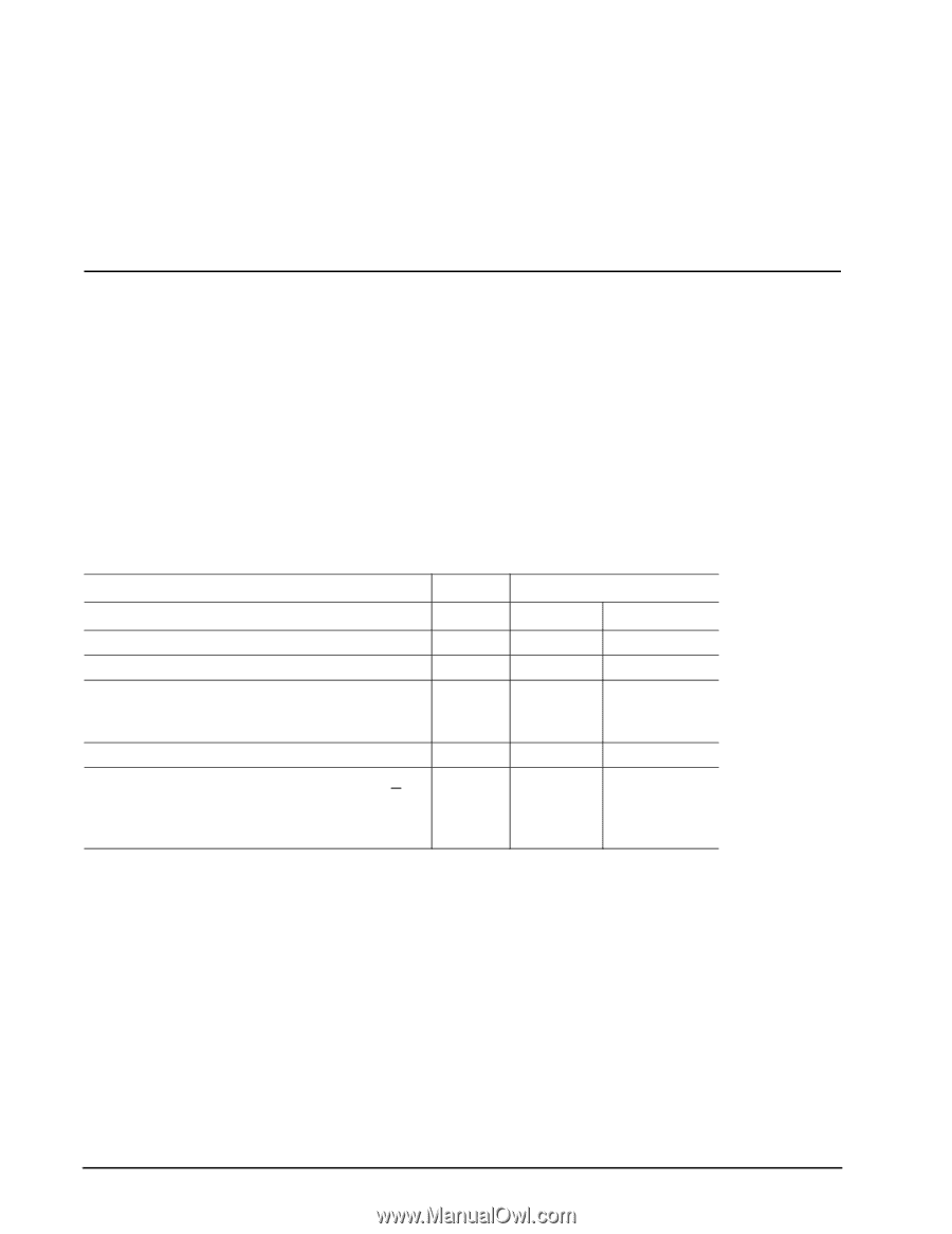
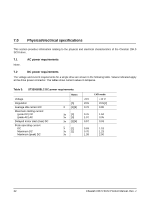
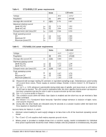
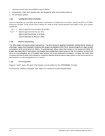
7.0 Physical/electrical specifications This section provides information relating to the physical and electrical characteristics of the Cheetah 15K.5 SCSI drive. 7.1 None. AC power requirements 7.2 DC power requirements The voltage and current requirements for a single drive are shown in the following table. Values indicated apply at the drive power connector. The tables show current values in Amperes. Table 3: ST3300655LC DC power requirements Voltage Regulation Average idle current DC Maximum starting current (peak DC) DC (peak AC) AC Delayed motor start (max) DC Peak operating current DC Maximum DC Maximum (peak) DC Notes [5] X [1][6] 3σ [3] 3σ [3] 3σ [1][4] X [1] 3σ [1] 3σ +5 V ±5% 0.70 LVD mode +12 V ±5% [2] 0.80 0.76 1.94 1.07 3.35 0.57 0.03 0.69 1.18 0.70 1.23 1.38 2.90 22 Cheetah 15K.5 SCSI Product Manual, Rev. J
-
 1
1 -
2
-
3
-
4
-
5
-
6
-
7
-
8
-
9
-
10
-
11
-
12
-
13
-
14
-
15
-
16
-
17
-
18
-
19
-
20
-
21
-
22
-
 23
23 -
 24
24 -
 25
25 -
 26
26 -
 27
27 -
 28
28 -
 29
29 -
 30
30 -
 31
31 -
 32
32 -
 33
33 -
34
-
35
-
36
-
37
-
38
-
39
-
40
-
41
-
42
-
43
-
44
-
45
-
46
-
47
-
48
-
49
-
50
-
51
-
52
-
53
-
54
-
55
-
56
-
57
-
58
-
59
-
60
-
61
-
62
-
63
-
64
-
65
-
66
-
67
-
68
-
69
-
70
-
71
-
72
-
73
-
74
-
75
-
76
-
77
-
78
-
79
-
80
-
81
-
82
-
83
-
84
-
85
-
86
-
87
-
88
 |
 |