Seagate ST3300457FC Cheetah 15K.5 SCSI Product Manual - Page 65
SCSI interface cable requirements, 6.3.1, Cable requirements, LC Models, Mating connectors, Table 16
 |
View all Seagate ST3300457FC manuals
Add to My Manuals
Save this manual to your list of manuals |
Page 65 highlights
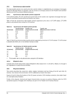
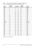
Table 16 shows the interface transfer rates supported by the various drive models defined in this manual. Table 16: Interface transfer rates supported Interface type/ drive models SE ST3300655LW/LC ST3146855LW/LC ST373455LW/LC LVD ST3300655LW/LC ST3146855LW/LC ST373455LW/LC Maximum transfer rate Asynchronous Fast-5 Fast-10 Fast-20 (Ultra) Fast-40 (Ultra2) Fast-80 (Ultra160) yes yes yes yes no no yes yes yes yes yes yes Fast-160 (Ultra320) no yes 10.6.3 SCSI interface cable requirements The characteristics of cables used to connect parallel interface drives are discussed in the ANSI standards referenced in this section. 10.6.3.1 Cable requirements The characteristics of cables used to connect Ultra320 SCSI parallel interface devices are discussed in detail in Section 6 of ANSI Standard T10/1365D Rev. 3. The cable characteristics that must be considered when interconnecting the drives described in this manual in a Ultra320 SCSI parallel, daisy-chain interconnected system are: • characteristic impedance (see T10/1365D Sections 6.3.3 and 6.3.4) • propagation delay (see T10/1365D Sections 6.3.6 and 6.3.7) • stub length (see T10/1365D Section 6.9) • device spacing (see T10/1365D Section 6.9) To minimize discontinuances and signal reflections, cables of different impedances should not be used in the same bus. Implementations may require trade-offs in shielding effectiveness, cable length, number of loads and spacing, transfer rates, and cost to achieve satisfactory system operation. If shielded and unshielded cables are mixed within the same SCSI bus, the effect of impedance mismatch must be carefully considered. Proper impedance matching is especially important in order to maintain adequate margin at FAST-20, FAST40, FAST-80, and FAST-160 SCSI transfer rates. Note. For LVD operation, twisted pair cables are recommended. For LVD Fast-40 operation, twisted pair cables are strongly recommended. For Fast-80 and Fast-160 operation, twisted pair cables are required. LC Models The 80-pin connector option provided on LC models is intended for use on drives that plug directly into backplane connector in the host equipment. In such installations, all backplane wiring segments are subject to the electromagnetic concepts presented in Standard T10/1365D, Rev. 3, Section 6. For LC model drives, installations with connectors on cables are not recommended. 10.6.4 Mating connectors Part numbers for the different type connectors that mate with the various Cheetah 15K.5 SCSI I/O connectors are given in the sections following. Cheetah 15K.5 SCSI Product Manual, Rev. J 59
-
 1
1 -
2
-
3
-
4
-
5
-
6
-
7
-
8
-
9
-
10
-
11
-
12
-
13
-
14
-
15
-
16
-
17
-
18
-
19
-
20
-
21
-
22
-
23
-
24
-
25
-
26
-
27
-
28
-
29
-
30
-
31
-
32
-
33
-
34
-
35
-
36
-
37
-
38
-
39
-
40
-
41
-
42
-
43
-
44
-
45
-
46
-
47
-
48
-
49
-
50
-
51
-
52
-
53
-
54
-
55
-
56
-
57
-
58
-
59
-
 60
60 -
 61
61 -
 62
62 -
 63
63 -
 64
64 -
 65
65 -
 66
66 -
 67
67 -
 68
68 -
 69
69 -
 70
70 -
71
-
72
-
73
-
74
-
75
-
76
-
77
-
78
-
79
-
80
-
81
-
82
-
83
-
84
-
85
-
86
-
87
-
88
 |
 |