Seagate ST3300457FC Cheetah 15K.5 SCSI Product Manual - Page 46
Alternate, Usage Plug
 |
View all Seagate ST3300457FC manuals
Add to My Manuals
Save this manual to your list of manuals |
Page 46 highlights
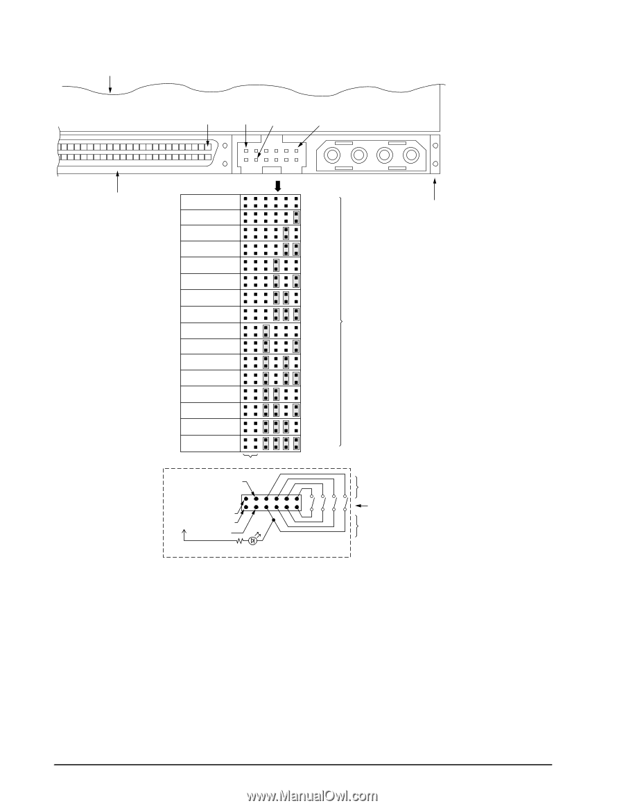
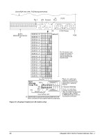
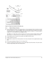
Drive HDA (rear view, PCB facing downward) Pin 1 +5V Ground J5 Pin 1 [1] [2] 4P 3P 2P 1P [2] J1-DC Power 68 Pin SCSI I/O Connector J1 SCSI ID = 0 SCSI ID = 1 SCSI ID = 2 (default) PCB SCSI ID = 3 SCSI ID = 4 SCSI ID = 5 SCSI ID = 6 SCSI ID = 7 SCSI ID = 8 SCSI ID = 9 For ID selection use jumpers as shown or connect a cable for remote switching as shown below. SCSI ID = 10 SCSI ID = 11 SCSI ID = 12 SCSI ID = 13 SCSI ID = 14 SCSI ID = 15 Reserved A3 A2 A1A0 Host Alternate N.C. Usage Plug 11 9 7 5 3 1 [4] A0 A1 A2 A3 +5V 12 10 8 6 4 2 +5V N.C. Ground Drive Activity LED [4] Dashed area is optional host circuitry (external to the drive) connected to host supplied optional usage plug. Pins 1, 3, 5, and 7 are optional connections to switching circuits in host equipment to establish drive ID. Remote Switches Pins 2, 4, 6, and 8 are normally not grounded. They are driven low (ground) for 250 ms after a Reset or PWR ON to allow drive to read SCSI ID selected. Figure 10. J5 jumper header (on LW models only) 40 Cheetah 15K.5 SCSI Product Manual, Rev. J
-
 1
1 -
2
-
3
-
4
-
5
-
6
-
7
-
8
-
9
-
10
-
11
-
12
-
13
-
14
-
15
-
16
-
17
-
18
-
19
-
20
-
21
-
22
-
23
-
24
-
25
-
26
-
27
-
28
-
29
-
30
-
31
-
32
-
33
-
34
-
35
-
36
-
37
-
38
-
39
-
40
-
 41
41 -
 42
42 -
 43
43 -
 44
44 -
 45
45 -
 46
46 -
 47
47 -
 48
48 -
 49
49 -
 50
50 -
 51
51 -
52
-
53
-
54
-
55
-
56
-
57
-
58
-
59
-
60
-
61
-
62
-
63
-
64
-
65
-
66
-
67
-
68
-
69
-
70
-
71
-
72
-
73
-
74
-
75
-
76
-
77
-
78
-
79
-
80
-
81
-
82
-
83
-
84
-
85
-
86
-
87
-
88
 |
 |