Seagate ST3300655LC Cheetah 15K.5 SCSI Product Manual - Page 29
Table 4, ST3146855LC DC power requirements, Table 5, ST373455LC DC power requirements
 |
View all Seagate ST3300655LC manuals
Add to My Manuals
Save this manual to your list of manuals |
Page 29 highlights
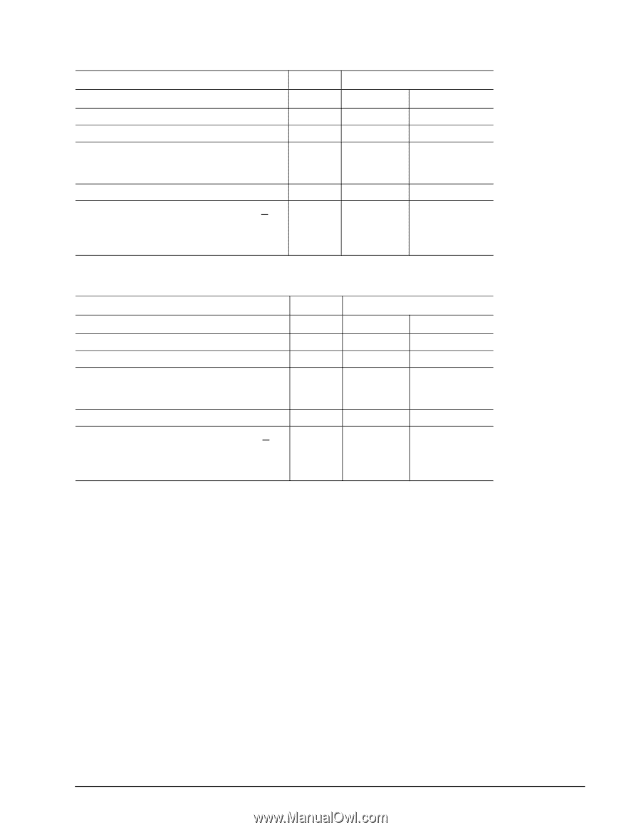
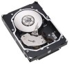
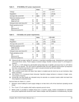
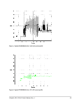
Table 4: ST3146855LC DC power requirements Voltage Regulation Average idle current DC Maximum starting current (peak DC) DC (peak AC) AC Delayed motor start (max) DC Peak operating current DC Maximum DC Maximum (peak) DC Notes [5] X [1][6] 3σ [3] 3σ [3] 3σ [1][4] X [1] 3σ [1] 3σ +5 V ±5% 0.71 0.74 1.04 0.56 0.67 0.68 1.42 LVD mode +12 V ±5% [2] 0.57 1.94 3.32 0.03 0.88 0.94 2.50 Table 5: ST373455LC DC power requirements Voltage Regulation Average idle current DC Maximum starting current (peak DC) DC (peak AC) AC Delayed motor start (max) DC Peak operating current DC Maximum DC Maximum (peak) DC Notes [5] X [1][6] 3σ [3] 3σ [3] 3σ [1][4] X [1] 3σ [1] 3σ +5 V ±5% 0.69 0.72 1.00 0.56 0.67 0.68 1.40 LVD mode +12 V ±5% [2] 0.42 1.94 3.32 0.03 0.78 0.82 2.38 [1] Measured with average reading DC ammeter or equivalent sampling scope. Instantaneous current peaks will exceed these values. Power supply at nominal voltage. Number of drives tested = 6, 35 Degrees C ambient. [2] For +12 V, a -10% tolerance is permissible during initial start of spindle, and must return to ±5% before 15,000 rpm is reached. The ±5% must be maintained after the drive signifies that its power-up sequence has been completed and that the drive is able to accept selection by the host initiator. [3] See +12 V current profile in Figure 1. [4] This condition occurs when the Motor Start Option is enabled and the drive has not yet received a Start Motor command. [5] See Section 7.2.1 "Conducted Noise Immunity." Specified voltage tolerance is inclusive of ripple, noise, and transient response. [6] During idle, the drive heads are relocated every 60 seconds to a random location within the band from three-quarters to maximum track. General Notes for Tables 3, 4, and 5: 1. Minimum current loading for each supply voltage is not less than 1.2% of the maximum operating current shown. 2. The +5 and +12 volt supplies shall employ separate ground returns. 3. Where power is provided to multiple drives from a common supply, careful consideration for individual drive power requirements should be noted. Where multiple units are powered on simultaneously, the peak Cheetah 15K.5 SCSI Product Manual, Rev. J 23
-
 1
1 -
2
-
3
-
4
-
5
-
6
-
7
-
8
-
9
-
10
-
11
-
12
-
13
-
14
-
15
-
16
-
17
-
18
-
19
-
20
-
21
-
22
-
23
-
 24
24 -
 25
25 -
 26
26 -
 27
27 -
 28
28 -
 29
29 -
 30
30 -
 31
31 -
 32
32 -
 33
33 -
 34
34 -
35
-
36
-
37
-
38
-
39
-
40
-
41
-
42
-
43
-
44
-
45
-
46
-
47
-
48
-
49
-
50
-
51
-
52
-
53
-
54
-
55
-
56
-
57
-
58
-
59
-
60
-
61
-
62
-
63
-
64
-
65
-
66
-
67
-
68
-
69
-
70
-
71
-
72
-
73
-
74
-
75
-
76
-
77
-
78
-
79
-
80
-
81
-
82
-
83
-
84
-
85
-
86
-
87
-
88
 |
 |