Seagate ST3300655LC Cheetah 15K.5 SCSI Product Manual - Page 62
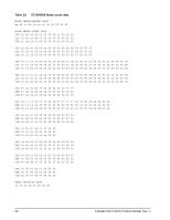
Synchronous data transfer periods supported, Table 14, Synchronous DT DATA transfer periods, Table
 |
View all Seagate ST3300655LC manuals
Add to My Manuals
Save this manual to your list of manuals |
Page 62 highlights
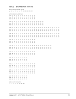
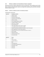
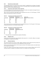
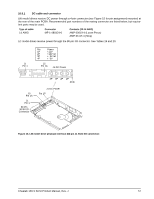
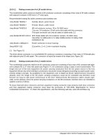
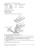
10.5 Synchronous data transfer The data transfer period to be used by the drive and the initiator is established by an exchange of messages during the Message Phase of operation. See the section on message protocol in the Parallel SCSI Interface Manual and SCSI Commands Reference Manual. 10.5.1 Synchronous data transfer periods supported In the following tables, M is the synchronous period value (in the transfer rate negotiation message) that represents the associated transfer period and transfer rate values. Table 14 lists the synchronous data transfer periods supported by the drive in DT DATA phase. DT DATA phase is only allowed when using the LVD interface. Table 14: Synchronous DT DATA transfer periods M (decimal) Transfer period Transfer rate (nanoseconds) (megatransfers/second) 8 6.25 160.0 9 12.5 80.0 10 25 40.0 12 50 20.0 25 100 10.0 Transfer rate (MBytes/second) on wide bus 320.0 160.0 80.0 40.0 20.0 Table 15 lists the synchronous data transfer periods supported by the drive in ST DATA phase. ST DATA phase is allowed with either LVD or SE interface except as noted. Table 15: Synchronous ST DATA transfer periods M (decimal) Transfer period Transfer rate (nanoseconds) (megatransfers/second) 10 25 40.01 12 50 20.0 25 100 10.0 50 200 5.0 1. This transfer rate is only allowed when using the LVD interface. 10.5.2 REQ/ACK offset Cheetah 15K.5 SCSI family drives support REQ/ACK offset values from 7 to 63 (3Fh). Offsets of 1 through 6 are negotiated to 0 (asynchronous transfer). 10.6 Physical interface This section describes the connectors, cables, signals, terminators and bus timing of the DC and SCSI I/O interface. See Section 10.8 and Section 10.9 for additional terminator information. Figures 13 and 14 show the locations of the DC power connector, SCSI interface connector, drive select headers, and option select headers. Details of the physical, electrical and logical characteristics are given in sections following, while the SCSI operational aspects of Seagate drive interfaces are given in the Parallel SCSI Interface Manual. 56 Cheetah 15K.5 SCSI Product Manual, Rev. J
-
 1
1 -
2
-
3
-
4
-
5
-
6
-
7
-
8
-
9
-
10
-
11
-
12
-
13
-
14
-
15
-
16
-
17
-
18
-
19
-
20
-
21
-
22
-
23
-
24
-
25
-
26
-
27
-
28
-
29
-
30
-
31
-
32
-
33
-
34
-
35
-
36
-
37
-
38
-
39
-
40
-
41
-
42
-
43
-
44
-
45
-
46
-
47
-
48
-
49
-
50
-
51
-
52
-
53
-
54
-
55
-
56
-
 57
57 -
 58
58 -
 59
59 -
 60
60 -
 61
61 -
 62
62 -
 63
63 -
 64
64 -
 65
65 -
 66
66 -
 67
67 -
68
-
69
-
70
-
71
-
72
-
73
-
74
-
75
-
76
-
77
-
78
-
79
-
80
-
81
-
82
-
83
-
84
-
85
-
86
-
87
-
88
 |
 |