Seagate ST336807FC Cheetah 10K.7 FC Product Manual - Page 58
LED connections
 |
View all Seagate ST336807FC manuals
Add to My Manuals
Save this manual to your list of manuals |
Page 58 highlights
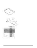
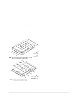
8.2 LED connections A connector, J6, is provided on the printed circuit board assembly (PCBA) to provide port bypass, drive active, and drive fault LED connections (see Figure 15). See Sections 9.5.7, 9.5.8, and 9.5.9 for descriptions of LED functions. J6 Figure 14. Physical interface Drive Front Pin 1 J6 Reserved Port A Bypass LED [1] Port B Bypass LED [1] Fault LED [1] Reserved Active LED [2] Reserved +5V Active LED [1] Ground [3] [1] The drive has a 1.2K ohm resistor in series with this LED driver. Tie the minus side of an external high-efficiency LED (i.e., 2ma) to this pin. Connect the plus side of the LED to +5V. [2] An external current-limiting resistor is required when connecting an LED to this pin. The minus side of the resistor/LED combination is connected to this pin. Connect the plus side to +5V. [3] Jumper storage location (across pins 2 and 4). Figure 15. LED indicator connector 46 Cheetah 10K.7 FC Product Manual, Rev. D
-
 1
1 -
2
-
3
-
4
-
5
-
6
-
7
-
8
-
9
-
10
-
11
-
12
-
13
-
14
-
15
-
16
-
17
-
18
-
19
-
20
-
21
-
22
-
23
-
24
-
25
-
26
-
27
-
28
-
29
-
30
-
31
-
32
-
33
-
34
-
35
-
36
-
37
-
38
-
39
-
40
-
41
-
42
-
43
-
44
-
45
-
46
-
47
-
48
-
49
-
50
-
51
-
52
-
 53
53 -
 54
54 -
 55
55 -
 56
56 -
 57
57 -
 58
58 -
 59
59 -
 60
60 -
 61
61 -
 62
62 -
 63
63 -
64
-
65
-
66
-
67
-
68
-
69
-
70
-
71
-
72
-
73
-
74
-
75
-
76
-
77
-
78
-
79
-
80
-
81
-
82
-
83
-
84
-
85
-
86
-
87
-
88
-
89
-
90
-
91
-
92
-
93
-
94
-
95
-
96
-
97
-
98
-
99
-
100
-
101
-
102
-
103
-
104
-
105
-
106
 |
 |
