Seagate ST336807FC Cheetah 10K.7 FC Product Manual - Page 88
Differential PECL input
 |
View all Seagate ST336807FC manuals
Add to My Manuals
Save this manual to your list of manuals |
Page 88 highlights
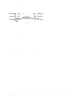
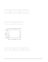
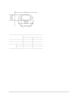
9.6.2 LED driver signals Fault and Active LED signals are located in the FC-SCA connector (J1) and through the indicator connector (J6). See Table 38 for the output characteristics of the LED drive signals. Table 38: LED drive signal State LED off, high LED on, low Current drive available 0 < IOH < 100µA IOL < -30 mA Output voltage 0 < VOL < 0.8V 9.6.3 Differential PECL output The serial PECL output signal voltage characteristics are provided in Table 39. The outputs are not AC coupled in order to deliver maximum signal without rise and fall time degradation. You must AC couple the receiver to isolate potentially different DC characteristics of the outputs and the receiver. Table 39: Differential PECL output characteristics Description Serial output voltage swing Parameter 600 < Vout < 1300 mV Figure 22 provides the data output valid eye diagram relative to the bit cell time. Table 41 lists the data values. Bit Time Vout (mv) XMIT Eye Figure 22. Transmit eye diagram 9.6.4 Differential PECL input The serial PECL input signal voltage characteristics are provided in Table 40. Table 40: Differential PECL input characteristics Description Serial input voltage swing Parameter 400 < Vin < 2.000 mV Notes AC coupled 76 Cheetah 10K.7 FC Product Manual, Rev. D
-
 1
1 -
2
-
3
-
4
-
5
-
6
-
7
-
8
-
9
-
10
-
11
-
12
-
13
-
14
-
15
-
16
-
17
-
18
-
19
-
20
-
21
-
22
-
23
-
24
-
25
-
26
-
27
-
28
-
29
-
30
-
31
-
32
-
33
-
34
-
35
-
36
-
37
-
38
-
39
-
40
-
41
-
42
-
43
-
44
-
45
-
46
-
47
-
48
-
49
-
50
-
51
-
52
-
53
-
54
-
55
-
56
-
57
-
58
-
59
-
60
-
61
-
62
-
63
-
64
-
65
-
66
-
67
-
68
-
69
-
70
-
71
-
72
-
73
-
74
-
75
-
76
-
77
-
78
-
79
-
80
-
81
-
82
-
 83
83 -
 84
84 -
 85
85 -
 86
86 -
 87
87 -
 88
88 -
 89
89 -
 90
90 -
 91
91 -
 92
92 -
 93
93 -
94
-
95
-
96
-
97
-
98
-
99
-
100
-
101
-
102
-
103
-
104
-
105
-
106
 |
 |
