Seagate ST9146853SS Savvio 15K.1 SAS Product Manual - Page 56
SAS Interface Manual
 |
View all Seagate ST9146853SS manuals
Add to My Manuals
Save this manual to your list of manuals |
Page 56 highlights
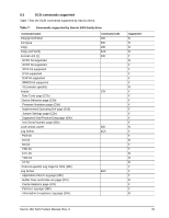
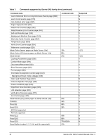
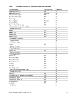
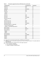
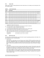
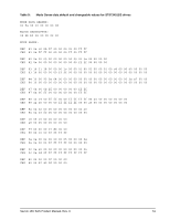
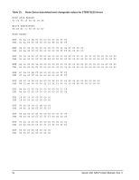
On drives requiring unique saved values, the required unique saved values are stored into the saved values storage location on the media prior to shipping the drive. Some drives may have unique firmware with unique default values also. On standard OEM drives, the saved values are taken from the default values list and stored into the saved values storage location on the media prior to shipping. 3. Current values Current values are volatile values being used by the drive to control its operation. A Mode Select command can be used to change the values identified as changeable values. Originally, current values are installed from saved or default values after a power on reset, hard reset, or Bus Device Reset message. 4. Changeable values Changeable values form a bit mask, stored in nonvolatile memory, that dictates which of the current values and saved values can be changed by a Mode Select command. A one (1) indicates the value can be changed. A zero (0) indicates the value is not changeable. For example, in Table 9, refer to Mode page 81, in the row entitled "CHG." These are hex numbers representing the changeable values for Mode page 81. Note in columns 5 and 6 (bytes 04 and 05), there is 00h which indicates that in bytes 04 and 05 none of the bits are changeable. Note also that bytes 06, 07, 09, 10, and 11 are not changeable, because those fields are all zeros. In byte 02, hex value FF equates to the binary pattern 11111111. If there is a zero in any bit position in the field, it means that bit is not changeable. Since all of the bits in byte 02 are ones, all of these bits are changeable. The changeable values list can only be changed by downloading new firmware into the flash E-PROM. Note. Because there are often several different versions of drive control firmware in the total population of drives in the field, the Mode Sense values given in the following tables may not exactly match those of some drives. The following tables list the values of the data bytes returned by the drive in response to the Mode Sense command pages for SCSI implementation (see the SAS Interface Manual ). DEF = Default value. Standard OEM drives are shipped configured this way. CHG = Changeable bits; indicates if default value is changeable. 50 Savvio 15K SAS Product Manual, Rev. C
-
 1
1 -
2
-
3
-
4
-
5
-
6
-
7
-
8
-
9
-
10
-
11
-
12
-
13
-
14
-
15
-
16
-
17
-
18
-
19
-
20
-
21
-
22
-
23
-
24
-
25
-
26
-
27
-
28
-
29
-
30
-
31
-
32
-
33
-
34
-
35
-
36
-
37
-
38
-
39
-
40
-
41
-
42
-
43
-
44
-
45
-
46
-
47
-
48
-
49
-
50
-
 51
51 -
 52
52 -
 53
53 -
 54
54 -
 55
55 -
 56
56 -
 57
57 -
 58
58 -
 59
59 -
 60
60 -
 61
61 -
62
-
63
-
64
-
65
-
66
-
67
-
68
-
69
-
70
-
71
-
72
-
73
-
74
-
75
-
76
-
77
-
78
-
79
-
80
-
81
-
82
-
83
-
84
 |
 |