Seagate ST9146853SS Savvio 15K.1 SAS Product Manual - Page 73
Compliance interconnect test load
 |
View all Seagate ST9146853SS manuals
Add to My Manuals
Save this manual to your list of manuals |
Page 73 highlights
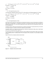
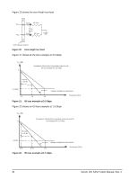
S21 = -20 × log10(e) × ((6, 5 × 10⁻⁶ × f0, 5) + (2, 0 × 10-10 × f) + (3, 3 × 10-20 × f2)) dB for 50 MHz < f < 1.5 GHz, and: S21 = -5, 437dB for 1.5 GHz < f < 5.0 GHz, where: a) f is the signal frequency in hertz. The transmission magnitude response of the TCTF in dB is given by the following equation for 3.0 Gbps: S21 = -20 × log10(e) × ((6, 5 × 10⁻⁶ × f0, 5) + (2, 0 × 10-10 × f) + (3, 3 × 10-20 × f2)) dB for 50 MHz < f < 3.0 GHz, and: S21 = -10, 884dB for 3.0 GHz < f < 5.0 GHz, where: a) f is the signal frequency in hertz. The TCTF is used to specify the requirements on transmitters that may or may not incorporate pre-emphasis or other forms of compensation. A compliance interconnect is any physical interconnect with loss equal to or greater than that of the TCTF at the above frequencies that also meets the ISI loss requirements shown in figure 21 and figure 22. Compliance with the TCTF test load requirement is verified by measuring the signal produced by the transmitter through a physical compliance interconnect attached to the transmitter. Compliance with the zero-length test load requirement verified by measurement made across a load equivalent to the zero-length load shown in figure 20. For both test load cases, the transmitter delivers the output voltages and timing listed in table 18 at the designated compliance points. The default mask is IR for intra-cabinet TxRx connections. The eye masks are shown in 9.5.2.1. Figure 19 shows the compliance interconnect test load. Tx+ Tx- TCTF 10 nF 50 ohm Probe points 10 nF 50 ohm SAS internal connector Figure 19. Compliance interconnect test load Savvio 15K SAS Product Manual, Rev. C 67
-
 1
1 -
2
-
3
-
4
-
5
-
6
-
7
-
8
-
9
-
10
-
11
-
12
-
13
-
14
-
15
-
16
-
17
-
18
-
19
-
20
-
21
-
22
-
23
-
24
-
25
-
26
-
27
-
28
-
29
-
30
-
31
-
32
-
33
-
34
-
35
-
36
-
37
-
38
-
39
-
40
-
41
-
42
-
43
-
44
-
45
-
46
-
47
-
48
-
49
-
50
-
51
-
52
-
53
-
54
-
55
-
56
-
57
-
58
-
59
-
60
-
61
-
62
-
63
-
64
-
65
-
66
-
67
-
 68
68 -
 69
69 -
 70
70 -
 71
71 -
 72
72 -
 73
73 -
 74
74 -
 75
75 -
 76
76 -
 77
77 -
 78
78 -
79
-
80
-
81
-
82
-
83
-
84
 |
 |
